GermanMafia
New Member
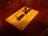
Alright I'm trying to build the AaronCake Chaser LED circuit
https://www.aaroncake.net/circuits/chaser.htm
Now I'm having a few difficulties (i just put it together for the most part tonight, haven't soldered the LED's yet and am trying to figure out which connections I need to solder to on my potentiometer).
So I'm looking at the circuit, there's no -9v. The negative poles on the LEDs drive straight into the ground, and the ground is 0v. Now I am pretty bad at electronic circuitry, so I may be missing something, but something just does not seem right about this. Also for the ground, how do you "make" a ground? I have all my grounds going into the long strip on my Radioshack IC board.
So to sum it up
*Where's the -9v?
*How do I go about creating a ground? (I read this https://en.wikipedia.org/wiki/Virtual_ground but dear god it was over my head).
*Well I guess that's it, look at how big of a windbag I am, all that typing for those two simple questions.