Continue to Site

Welcome to our site!

Electro Tech is an online community (with over 170,000 members) who enjoy talking about and building electronic circuits, projects and gadgets. To participate you need to register. Registration is free. Click here to register now.

  • Welcome to our site! Electro Tech is an online community (with over 170,000 members) who enjoy talking about and building electronic circuits, projects and gadgets. To participate you need to register. Registration is free. Click here to register now.

[noob] is there any better way to drive this mosfets?

Status
Not open for further replies.
hi, i'm progressing in my fan and peltrier controler for my pc, and have an already working circuit, but the problem is that it sucks 6W just tu keep the this off. (big 10W resistor....)
**broken link removed**

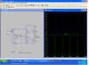
this is the old circuit that i have builded in a breadboard. and works great so great that the flyback diode blew when i pluged in a toy car motor to test if the heatsink could stand the heat......
(those brush motor must have a very high inverse current)

the problem is that those resistor are AAA-batery size, and get very hot, and if i want to fit this in a 5 1/2 bay then i have to keep everything as small and cool as posible.

the new circuit is this. using some npn and pnp driven with a smal 1/4 watt resistor.
**broken link removed**

the 2N6038 will be a TIP102.

is there anything better? the idea is to have a response around 1 or 1/2 µs.

PS: the pwm signal works at 25KHz, and i don't have an oscilosope yet u.u
 
Last edited:
How about a FET driver like this? Then 1 FET on a small heatsink should be enough.

http://www.clare.com/home/pdfs.nsf/0/7CE9573FE423CA5D8525775200518698/$file/IXD_604.pdf
 
the problem is that it's quite dificult to me to find that kind of ICs here...... :(
the only one i find is the IR211 but i dont quite understand how to use it.....i'll see if i can find some info on how to use them.

and, i dont think one small heatsink will be enough, remember i said peltrier, and that about 8A(96W), it will be controled by a pic to keep it at about ambient temperature to avoid condensation but ill have to calculate it for the worst case. same for the fans., i plan to use some that suck up to 3A. (36W)
 
Last edited:
yes, that's what i did in the second attemp with two power darlingtons
**broken link removed** (look at the osciloscope, about .5µs till 12V)

i used 2 totem poles, one inverting and amplifing the pwm signal, to be able to get a 12V signal (which inverts the signal again) and then another totem pole to feed the gates.

the resistor u see ther is a 576....lets say 580 ohms to be able to use a 1/4W resistor, but i may as well use a 1/2W or 1W, it dependes on how hot it gets, i'll do some testings later to see it can withtand 1/4W continuesly

EDIT: 51ºC after 2min and holded ther another 10min.

and just out of curiosity tryed the 10w one from the old circuit too........130ºC after 4min and holded there.
 
Last edited:
...and, i dont think one small heatsink will be enough, remember i said peltrier, and that about 8A(96W), it will be controled by a pic to keep it at about ambient temperature to avoid condensation but ill have to calculate it for the worst case. same for the fans., i plan to use some that suck up to 3A. (36W)

Cooling electronics using a Peltier element of 96W will take you into deep sh.t. No matter how low the Peltier temperature will be - it will be low enough to produce condensed water.

Here is an example I experienced: Tamb=35deg/C, TPel=25deg/C - result: dripping water from the heat sink right into my wireless internet modem.

Using a tunnel type heat sink with a good fan you won't have that trouble. There are tunnel type heat sinks with a thermal resistance of <0.2deg/K/W

Boncuk
 
yeah i know, that's why all will be controled by a pic, to keep the cold side of the peltrier above ambient temperature, to avoid condensation, forgot to mention it.
furthermore the idea is to use the pic to calculate the frecuency and the duty cycle lenght and use that data to make a pwm signal at 50khz (when controling fans without out the pwm wire), that will stop the coils inside the fans from making that anoying buzz with medium to high powered fans.

the idea of using the peltrier is to be able to use a low cost heat sink like my cooler master 212+ to cool everything far better without investing much more. or having to buy one uber big heatsink with which u have to buy an extra large case to fit it, etc. and it also helps if you are building a fanless system.
 
Last edited:
Driver

the problem is that it's quite dificult to me to find that kind of ICs here...... :(

Here is a simpler totem pole driver similar to what Mr. T suggested.
i dont think one small heatsink will be enough, remember i said peltrier, and that about 8A(96W)

The peltier may dissipate 96 watts but the FET is only .0175 ohms when on, so 8x8x.0175=1.12 watts.
 

Attachments

  • totem pole driver.PNG
    totem pole driver.PNG
    71.3 KB · Views: 945
i didn't know that about the resistance and the heat disipation, thanks.

and about the totem pole, that's the same as before but i got confused myseft with some stuff about the bjt reverse base emiter breackdown voltages.....i thouth it was the maximum voltage for everything...silly me xD
just found out yesterday, so....i'll give a revision :p

edit: it works but the first transistor belor the 47ohm resistor overheats like hell, tried till it got above 154ºC, so remplaced it with the tip102,
now it works,don't know the response curve.. but it works as far as my sight can see
 
Last edited:
yeah i just realised it was the reverse breakdown voltage. i didn't had a schotky at the beggining, so i didn't use it (and as it worked fine, didn't care) , but back them it was with 5V, and that's the limit, but now with 12V the 12V from the gate passed througt the emitter-base from Q3 instead of Q2, my bad again :(
inserted a ultrafast schottky and solved the problem...
 
Status
Not open for further replies.

Latest threads

Back
Top