I am building a ultrasound recevier circuit based on a electrostatic transducer. The transducer requires a 200V DC bias in order to operate.
At the output of the transducer, I used 2 simple RC filter stage. The first stage is a high pass filter that removes the 200V DC bias voltage. The second stage is a low pass filter that filters away the high frequency noise from the DC-DC converter.
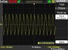
However, it seems like I am still getting a 200 mVpp 146 kHz noise component. I can only see my received signal which is at 50 kHz 20 mVpp when I use a digital filter on my oscilloscope.
Anyone can help suggest how to improve the signal to noise ratio? I am using a DC-DC converter from Hitek (Model: GMA 12-200PE). I have also attached my schematic in the post.
At the output of the transducer, I used 2 simple RC filter stage. The first stage is a high pass filter that removes the 200V DC bias voltage. The second stage is a low pass filter that filters away the high frequency noise from the DC-DC converter.
However, it seems like I am still getting a 200 mVpp 146 kHz noise component. I can only see my received signal which is at 50 kHz 20 mVpp when I use a digital filter on my oscilloscope.
Anyone can help suggest how to improve the signal to noise ratio? I am using a DC-DC converter from Hitek (Model: GMA 12-200PE). I have also attached my schematic in the post.