Electro Tech is an online community (with over 170,000 members) who enjoy talking about and building electronic circuits, projects and gadgets. To participate you need to register. Registration is free. Click here to register now.
Welcome to our site! Electro Tech is an online community (with over 170,000 members) who enjoy talking about and building electronic circuits, projects and gadgets. To participate you need to register. Registration is free. Click here to register now.
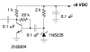
A zener diode is noisy. A Google search on zener diode noise may turn up some info on it. I have used a circuit like this to check CB radios (11 mHz), so the frequency is wide band.
It's the base bias resistor for the transistor, it also provides a degree of both AC and DC negative feedback - this allows you not to have to select the resistor value for the particular specimen of transistor you use. However, it does reduce the gain of the amplifier, due to the AC feedback.
It's the base bias resistor for the transistor, it also provides a degree of both AC and DC negative feedback - this allows you not to have to select the resistor value for the particular specimen of transistor you use. However, it does reduce the gain of the amplifier, due to the AC feedback.
The gain is reduced if the source impedance is significant. However, since the source impedance is only a few ohms, the mid-band gain is actually not affected much by the feedback resistor. What IS affected is the bandwidth (low frequency corner). The feedback lowers the input resistance. Simulation shows the low frequency corner to be about 16kHz! Not very useful if you want audio noise. The input cap needs to be increased to at least 10uF if audio noise is desired.
So the feedback resistor is for narrowing the noise frequency band!!!
u sadi that the simulation gave that the frequency is 16KHz ,,,,
how could u get this specific frequency although there is no kind of filters or frequency selectors??
another thing..... this Transistor is for amplifying the nosie ,,,, in my ciruit after the the transistor there is an Op Amp. .... then could it be that this transistor has another job beside the amplification??
The purpose of the feedback resistor is not "lowering the noise frequency band". The purpose is to provide base bias current.
The 0.1uF input cap, in conjunction with the input resistance of the amplifier, form a highpass filter. See the plots below. I show what happens if you change the input cap to 10uF.
The transistor has no purpose other than amplification. If you follow it with an op amp as a linear amplifier (not as a comparator, or limiter), you may not need the transistor. However, eliminating the transistor amplifier will mean you have to run the op amp at about 100 times as much gain in order to get the same signal level. This will lower the high frequency bandwidth by the same ratio.
Here is a **broken link removed**, which is supposed to be useful for audio testing. I uses a zener (reverse-biased base-emitter junction) as the noise source. A Google search for "pink noise generator" and "white noise generator" will get you lots of hits.
Perhaps Audioguru or Nigel Goodwin would have some further suggestions. I'm no audio guru.
Yes, the noise from a zener is effectively 'white' noise. For audio testing purposes 'pink' noise is of more use, the link already posted shows how to generate that (by simply filtering 'white' noise).
hi all,
i happened to join the forum a bit late. but i think i hav sme useful info on the Zener noise stuff.consider just a simple diode and a resistor in series (the diode in forward bias condition)connected to a power supply .suppose we increase the supply voltage .then th current through the resistor increases because we have the same no of electrons travelling at a higher velocity. now through the diode the current increase is because of the increase in the no of electrons.since velocity can take any value the current through the resistor can hav any value but the current through the diode is discretized. so there is a mismatch.this leads to fluctuations in the output taken across the diode.
if anyone has found any literature pertaining to this on the web please forward the address
This site uses cookies to help personalise content, tailor your experience and to keep you logged in if you register.
By continuing to use this site, you are consenting to our use of cookies.

")