Continue to Site

Welcome to our site!

Electro Tech is an online community (with over 170,000 members) who enjoy talking about and building electronic circuits, projects and gadgets. To participate you need to register. Registration is free. Click here to register now.

  • Welcome to our site! Electro Tech is an online community (with over 170,000 members) who enjoy talking about and building electronic circuits, projects and gadgets. To participate you need to register. Registration is free. Click here to register now.

Nodal Analysis

Status
Not open for further replies.
Hello,


(See attached image below)


That diagram is not correct with respect to how it shows the currents
i1 and i2. The corrected diagram would look like that shown in
Figure 3 of the attached drawing.

Starting with the original diagram and ignoring the current arrows shown
as i1 and i2, we first label the node voltages as shown in Figure 1.

Next, we label the branch currents I1, I2, I3, and I4 as shown in Figure 2.
Note these are all upper case.

Next, we want to write the nodal equations, but we note that we already know
v1 and v2 so the only equation we need is for v3. That means we write one
nodal equation for v3:

(v1-v3)/14-(v3-v2)/10-v3/8=0


Since v1 and v2 are already known, substitute them into the equation:
(10-v3)/14-(v3-3)/10-v3/8=0

Now simplifying:
10/14-v3/14-v3/10+3/10-v3/8=0
100/140+42/140=v3*(1/14+1/10+1/8)
100/140+42/140=v3*(10/140+14/140+17.5/140)
100+42=v3*(10+14+17.5)
142=v3*41.5
142/41.5=v3

So we get:
v3=3.4216867469879518072289156626506

We now know all of the node voltages so we can calculate all of the
branch currents and that will allow us to calculate the real i1 and i2.

Now we calculate the currents I1, I2, I3, and I4:
I1=7/4=1.75 amps
I2=(10-v3)/14=0.46987951807228915662650602409639
I3=0.04216867469879518072289156626506
I4=0.42771084337349397590361445783133

Now we redraw the circuit as shown in figure 3 because i1 and i2
are not drawn correctly in the original diagram, and we see that
I2 is approximately 470ma, so i2 is 470ma. Also, since i1=I1+i2,
we get 2.22 amps for i1. That means we get:
i1=2.22 amps, and
i2=0.47 amps (approximate).
 

Attachments

  • Nodal-001.gif
    Nodal-001.gif
    242.2 KB · Views: 383
At the top of the image you posted it says:

"Chapter 4 Basic nodal and mesh analysis"

Then is shown a circuit with two mesh currents indicated. When the problem so obviously calls for a mesh analysis (since the unknown currents are mesh currents), why would you choose to use the nodal method to solve the network? Did your instructor direct you to use the nodal method on that particular problem?

MrAl says "That diagram is not correct with respect to how it shows the currents i1 and i2. " There's nothing wrong with how the currents are shown; they're mesh currents. It's perfectly ok to show mesh currents as unknowns in a network problem.

If you were to solve the network with the mesh analysis method, the answer obtained would be the indicated mesh currents directly.

You can certainly use the nodal method as MrAl showed, but then you may have to do some additional algebra to obtain the desired mesh currents from the node voltages.

When the practice problems at the end of a chapter about "Basic nodal and mesh analysis" are given, one might reasonably expect that you are supposed to use the appropriate method, nodal or mesh analysis, as suggested by the way they label the unknowns.
 
At the top of the image you posted it says:


MrAl says "That diagram is not correct with respect to how it shows the currents i1 and i2. " There's nothing wrong with how the currents are shown; they're mesh currents. It's perfectly ok to show mesh currents as unknowns in a network problem.

Hello,


There's nothing wrong with the currents if we were doing anything other than nodal analysis, but also
that can not be the currents they wanted to see solved for because i1 and i2 exactly as drawn will not
come out to 2.22 amps and 470ma as the answers tell us. The only way to get those values is to
assume that the currents are as shown in Figure 3. What i meant was that they must have used another
drawing to show the student and didnt bother to redraw where the currents to be solved for actually
would be found.
 
Last edited:
Hello,


There's nothing wrong with the currents if we were doing anything other than nodal analysis, but also
that can not be the currents they wanted to see solved for because i1 and i2 exactly as drawn will not
come out to 2.22 amps and 470ma as the answers tell us. The only way to get those values is to
assume that the currents are as shown in Figure 3. What i meant was that they must have used another
drawing to show the student and didnt bother to redraw where the currents to be solved for actually
would be found.

There is a third mesh that the problem doesn't ask about, but that mesh current can be included and the network can be solved by the mesh method. Let the current in the third mesh also be clockwise and denote it as i3. Then there are 3 equations:

4*i1 - 4*i2 + 0*i3 = 7
-4*i1 + 28*i2 -10*i3 = 0
0*i1 - 10*i2 + 18*i3 = 3

If these three equations are solved for i1, i2 and i3, you get:

i1 = 2.21987951807
i2 = .469879518072
i3 = .427710843373

i1 and i2 come out exactly as drawn.

i1 in your figure 3 is the current out of the 10 volt source, and that is exactly what the crossed out i1 in your figure 1 is (and the OP's image). Similarly, i2 in your figure 3 is the current in the 5 ohm resistor, and that is what the crossed out i2 in your figure 1 is (and in the OP's image).
 
Hello again,


Ok, but he was asking for nodal not mesh analysis right? That means the way those currents are drawn dont make sense.
Im sure what happened here was the original problem was using mesh analysis, then the student was asked to do the
circuit using nodal analysis later.
 
Last edited:
Hello again,


Ok, but he was asking for nodal not mesh analysis right? That means the way those currents are drawn dont make sense.

Why don't they make sense? Mesh currents are certainly most directly associated with a mesh analysis, but that doesn't make then nonsense in a nodal analysis, just less directly associated with the nodal solution. They can be calculated from the node voltages, as you did, and the student could be asked to determine them from a nodal analysis for the reason I mention below.

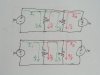
The current labeled i1 in your figure 3 is the current in the 10 volt source. The current labeled i1 in the OP's image is the current in the 10 volt source. They are the same current. If the current i1 in the OP's image doesn't make sense, then the current labeled i1 in your figure 3 also doesn't make sense; they are identical.

On the other hand, if the current i1 in your figure 3 makes sense, then the current i1 in the OP's image also makes sense; they are the same current.

Similarly for i2.

It should be possible to solve for any set of currents using any of the standard methods of network analysis. But it's quite typical for one method to be more convenient than another with a given network and a given set of desired currents, and one of the things a student of network analysis should learn is how to tell when one method might be better than another.

Im sure what happened here was the original problem was using mesh analysis, then the student was asked to do the
circuit using nodal analysis later.

I asked him about that, and he hasn't responded. The OP is just learning circuit analysis, and I think it's also possible that he just didn't recognize that when mesh currents are shown, the problem author is trying to give a hint as to an appropriate method of solution.

But I can also imagine an instructor directing a student to use an inappropriate method for the purpose of giving the student an object lesson as to the value of knowing how to decide the appropriate method.
 
Last edited:
Consider the circuit shown in the attachment. There are two identical 10 volt sources, two identical 10 ohm resistors and wires made of zero resistance unobtanium (which happens to be a superconductor).

We can see by inspection that there is 10 volts across each resistor, so each carries 1 amp. That's 2 amps total, which must come from the sources.

But, where does the current in each resistor come from? Does the current in the left hand resistor come only from the left hand source? Perhaps some current in each resistor comes from both sources. I've shown two possibilities in the image for how the current might divide. In both cases, the current in each resistor is 1 amp, which we know is what the actual physical current would be.

Is there any reason to say that only one way for the currents to divide makes sense, and the others don't?

There are an infinite number of ways to decompose the actual currents, and for mathematical purposes some may be more convenient than others.

In mesh analysis, abstract mathematical currents are assumed to circulate around each mesh, and the real, physical, currents are always composed of linear combinations of the mesh currents. If one of the mesh currents happens to go through a single component, then that particular mesh current is also an actual physical current in value, as well as being a mathematical abstraction.

It's sort of like moving from the time domain to the frequency domain, making calculations or measurements, and then moving back to the time domain.

We move to the "mesh domain" to solve the problem (decompose the currents), then back to the "physical domain" with our final answer (recompose the currents). It makes sense.
 

Attachments

  • example.jpg
    example.jpg
    54.9 KB · Views: 346
Hello again,


Hey no problem, if you like doing it that way that's fine.
 
i dont know why you all guys did a long, just mark the unknown node as V1,
then we have
(V1-3)/10 + (V1-10)/14 + (V1-0)/8 = 0
so V1= 3.42V

so i1= (10-V1)/14 = 0.47A

(10-3)/4 = i1-i2
so i2= -1.28
 
Hello again,


Another interesting fact here is that nodal analysis is more general than mesh analysis, in that mesh analysis does not work for every circuit we can find whereas nodal does.
 
Hello again,


Another interesting fact here is that nodal analysis is more general than mesh analysis, in that mesh analysis does not work for every circuit we can find whereas nodal does.

I much prefer nodal analysis, but there are circuits that classical nodal analysis can't directly deal with, such as those involving transformers. A number of tricks have been used in the past to get around this limitation, but when Ruehli, et al, invented MNA (modified nodal analysis) in 1975, all limitations to the classical nodal method were eliminated.

When you say mesh analysis doesn't work for every circuit, you are probably alluding to the fact that non-planar networks are generally unsolvable with mesh analysis. But that limitation is readily removed by just going to loop analysis, which uses KVL in the same manner as mesh analysis.
 
Hello again,


mesh analysis does not work for every circuit we can find whereas nodal does.

i don't agree with it, we can use any of the method for all circuit we can find, but some can be easily solved by nodal method and some are by mesh
 
I much prefer nodal analysis, but there are circuits that classical nodal analysis can't directly deal with, such as those involving transformers. A number of tricks have been used in the past to get around this limitation, but when Ruehli, et al, invented MNA (modified nodal analysis) in 1975, all limitations to the classical nodal method were eliminated.

When you say mesh analysis doesn't work for every circuit, you are probably alluding to the fact that non-planar networks are generally unsolvable with mesh analysis. But that limitation is readily removed by just going to loop analysis, which uses KVL in the same manner as mesh analysis.

Yes of course, but then that's not mesh anymore.
 
i don't agree with it, we can use any of the method for all circuit we can find, but some can be easily solved by nodal method and some are by mesh


Actually, you can not analyze a non planar circuit using mesh analysis.

Attached is a non planar network. Note that there is one jumper where
one path must jump over another and that the network can not be
drawn without at least one jumper like that. That's because it is
non planar and so that means mesh analysis can not be used.
If you dont believe this for some reason you are welcome to try :)
 

Attachments

  • NonPlaner01.gif
    NonPlaner01.gif
    8.1 KB · Views: 564
Last edited:
it still can be solved by mesh analysis, imaginary current paths(mexwell) still can be noted for effective meshes and can be solved.
6 equation of 6 unknown currents yields for solutions.

but nodal method will have only 3 unknows and easy to work with.
 
Last edited:
Hello again,


Yes, some networks will be solvable as you say, but it's not a guarantee that the solutions will be valid for non planar circuits, thus the theory is that non planar networks should not be solved using mesh analysis.
The network shown is a non planar network and illustrates how to tell a planar network from a non planar network. It may not be non planar 'enough' to be unsolvable, but the only way to be sure is to use nodal analysis, and why bother to do both? In other words, if you use mesh analysis to do a non planar network you may come up with the wrong solutions so to check you would have to do a nodal as well. Instead of going through all that it is faster to do a nodal.

If you want to try to disprove the theory that a non planar network should not be solved by mesh analysis i would like to see this :)

A non planar network is defined as a network that can not be drawn on a two dimensional surface without crossing at least one line with another.
 
Status
Not open for further replies.

Latest threads

New Articles From Microcontroller Tips

Back
Top