Continue to Site

Welcome to our site!

Electro Tech is an online community (with over 170,000 members) who enjoy talking about and building electronic circuits, projects and gadgets. To participate you need to register. Registration is free. Click here to register now.

  • Welcome to our site! Electro Tech is an online community (with over 170,000 members) who enjoy talking about and building electronic circuits, projects and gadgets. To participate you need to register. Registration is free. Click here to register now.

Nocturnal solar circuit question

Status
Not open for further replies.

Myrmidon

New Member
Hello all.

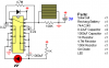
I'v made a small 555 timer light display for a shelf in my room to illuminate behind my collection of dragon statues. I have the circuit working fine and built, but i want it to charge batteries during the day and as it get's dark to come on at night.

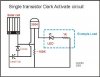
My question is, on the solarbotics site there are a few nocturnal solar engines which involve the solar cell, a diode and a resistor in parallel as the light detector. Would it just be a case of hooking that up to the power rails and off i go?

Included are my circuit and a solar example.
 

Attachments

  • 555 lightshow.JPG
    555 lightshow.JPG
    36 KB · Views: 186
  • BEP Pummer.png
    BEP Pummer.png
    4.8 KB · Views: 194
Please provide a link to the place you are talking about.

You probably haven't had any replies as no one knows what you're talking about.
 
Chuckle.

All i'm simply asking is, could i use the solar circuit from the second attachment, the beam pummer, which charges the batteries during the day and the in parallel resistor makes the solar cell act as a dark detector as well. Could i simply add that to my power supply of MY circuit so that it charges the batteries during the day and at night, the solar cell/dark detector kicks in and makes the light show activate at night.

Ross
 
Myrmidon said:
Chuckle.

All i'm simply asking is, could i use the solar circuit from the second attachment, the beam pummer, which charges the batteries during the day and the in parallel resistor makes the solar cell act as a dark detector as well. Could i simply add that to my power supply of MY circuit so that it charges the batteries during the day and at night, the solar cell/dark detector kicks in and makes the light show activate at night.

Ross

I don't think you understand the circuit. The 74HC240 is a octal buffer chip, there are two ENABLE pins, one for each group of 4 buffers. The solar cell controls the enable pin(s), the buffers are used as oscillators. The large capacitor and resistor are a charge-pump, makes the LED(any color, any wattage) flash really bright, off 2 AA batteries.

I couldn't find it, but think it came off the Solarbotics website... A simple one transistor switch, that uses the solar cell for a light sensor. Pretty sure it was posted on this forum a time or two for 'solar garden lights'.
 
I'm not using the chip though. I'm just using the solar cell, diode and parallel resistor bit and attaching it to the power supply on my circuit. I was just wondering if it would perform the same function for any circuit, ie charge batts during day, as solar cell voltage falls, power from the batteries kick in.

It seems to working so far on my circuit.
 
The diode is there to block the battery from discharging through the solar cell. The parallel resistor sets the level makes sure the ENABLE on the HC240 is brought low, to enable the buffers. Not sure how you are switching anything without the 74HC240. I went through the Pummer circuit pretty thoroughly to make an RGB version. Trust me, the enable pin is what turns it on at night, off in the day. Two buffers are need for an oscillator, so you could have 4 independent LEDs flashing off one chip.

You need atleast one transistor to switch your 555 circuit.
 
Okay... I did a quick search of the forum, and found the circuit I had in mind (attached).

Where it says 'large capacitor', you can replace it with batteries. Positive goes to the diode. Replace the LED and resistor with your 555 circuit. May need to change the 100k resistor...
 

Attachments

  • 2curcuits.jpg
    2curcuits.jpg
    57.7 KB · Views: 301
Status
Not open for further replies.

Latest threads

New Articles From Microcontroller Tips

Back
Top