Continue to Site

Welcome to our site!

Electro Tech is an online community (with over 170,000 members) who enjoy talking about and building electronic circuits, projects and gadgets. To participate you need to register. Registration is free. Click here to register now.

  • Welcome to our site! Electro Tech is an online community (with over 170,000 members) who enjoy talking about and building electronic circuits, projects and gadgets. To participate you need to register. Registration is free. Click here to register now.

No idea about problem

Status
Not open for further replies.

zhaniko93

New Member
I have Pic16f84A Code:
Code:
	list      p=16F84A            ; list directive to define processor
	#include <p16F84A.inc>        ; processor specific variable definitions
	errorlevel -302, -207


	__config _XT_OSC & _WDT_OFF & _CP_OFF
	;============ 
	; Declarations: 
	acc_level equ 0x0c
	Test	equ 0x0d


	#define	main_eng PORTA, 1
	#define	accel PORTB, 6
	#define	slow_down PORTB, 5

	clrf	acc_level
	clrf	PORTA		; resets Port A
	clrf	PORTB
	bsf	STATUS,RP0	; BANK1
	movlw	b'0000'		; RA0: LED, RA1-3: not connected
	movwf	TRISA
	movlw	b'01011011'
	movwf	TRISB

	movlw	0x0
	movwf	INTCON
	movlw	b'11010100'
	movwf	OPTION_REG

	bcf	STATUS, RP0
	;============ 


	Main	 
	movfw	acc_level
	movfw	Test
	btfsc	accel
	call	gazi
	btfsc	slow_down
	call	tormuzi
     ; Start Engine
     call Going
     call Going
      call Going
      call Going
      call Going
	goto	Main
		 
	Going	clrf TMR0
	bsf	main_eng
	Mda	movfw acc_level
	subwf	TMR0, 0
	btfss	STATUS, Z
	goto	Mda
	call	W8ing
	retlw	0

	W8ing	movfw TMR0
	sublw	0xFF
	bcf	main_eng
	movwf	Test
	decfsz	Test,F
	goto	W8ing
	retlw	0


	gazi	movfw acc_level
	sublw	0xFE
	btfss	STATUS, Z
	incf	acc_level,F
	retlw	0

	tormuzi	movfw acc_level
	sublw	0x00
	btfss	STATUS, Z
	decf	acc_level,F
	retlw	0


	end
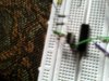
And Proteus Project, which I attached and the problem is that when I connect 5V to RB6 (accelerate), motor accelerates constantly but when I connect 5V to rb5(Decelerate), motor stops running imediatelly and I can't understand why.
 

Attachments

  • Picture 002.jpg
    Picture 002.jpg
    38.7 KB · Views: 268
  • Picture 001.jpg
    Picture 001.jpg
    26.8 KB · Views: 188
  • JaKo 16F84A.zip
    15.5 KB · Views: 178
hi,
RB5 is set as an Output,????
 

Attachments

  • AAesp02.gif
    AAesp02.gif
    8.6 KB · Views: 194
I downloaded your project file but could not open it to see the schematic so -

Do RB5 and RB6 have a pullup resistor on them?

What type of switch are you using to trigger RB5 and RB6 (i.e. Normally Open Momentary, Normally Closed Momentary, or a Latching switch)?

As was said before...you need to configure RB5 as an input as it is currently set up as an output. Once you can answer my questions regarding the pullup resistors and the accel/decel switches we can assist you further.
 
The problem was that RB5 was output :D
 
Status
Not open for further replies.

Latest threads

Back
Top