Electro Tech is an online community (with over 170,000 members) who enjoy talking about and building electronic circuits, projects and gadgets. To participate you need to register. Registration is free. Click here to register now.
Welcome to our site! Electro Tech is an online community (with over 170,000 members) who enjoy talking about and building electronic circuits, projects and gadgets. To participate you need to register. Registration is free. Click here to register now.
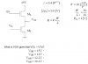
Considering a very small load, I'd choose 15V for VOH, given that Vin = 0V.
Anyway.
ML is an active load, it is probably biased in the saturation region (remember, for a FET saturated = BJT active). So it will act as a resistence.
Remember that the current through ML = the current through MI = I Total.
And, Vout = VDS (MI) = 15V - VDS (ML).
If MI is at cutoff (no current), then I total = 0 and VDS(ML) = 0 => Vout = 15V
Of course, as you increases Vin, the VDS(ML) is going to increase very little, but you would have to make the calculations. (Remember ID (ML) = ID (MI)).
I think that you meant that it is in the linear region.
I believe its in the linear region (VGS(L) - VTn(L) < VDS(L)) since:
ID(L) = 0A
=>
VGS(L) <= VTn(L)
If MI is at cutoff (no current), then I total = 0 and VDS(ML) = 0 => Vout = 15V
Why do you conduct that if ID(L) = 0A then VDS(L) = 0V?
It is enough that VGS(L) = VTn(L) (or just a bit less than VTn(L)) for ML not to pass current through its channel.
So Vout doesnt need to reach 15V for ID(L) to be 0A.
Ok, your simulation is not correct, because you are using 3-terminal MOSFETs, so that you have body-effect (reduced gain). (I'm not saying your result is wrong, just the way the simulation was made).
To simulate this circuit you MUST use 4-terminal MOSFETs and connect the body to the GND. And do not forget to consider the parameters given by the exercise.
This site uses cookies to help personalise content, tailor your experience and to keep you logged in if you register.
By continuing to use this site, you are consenting to our use of cookies.