Continue to Site

Welcome to our site!

Electro Tech is an online community (with over 170,000 members) who enjoy talking about and building electronic circuits, projects and gadgets. To participate you need to register. Registration is free. Click here to register now.

  • Welcome to our site! Electro Tech is an online community (with over 170,000 members) who enjoy talking about and building electronic circuits, projects and gadgets. To participate you need to register. Registration is free. Click here to register now.

Nigel, ronsimpson, come here please! It is working!

Status
Not open for further replies.

sram

Member
Hello, this is regarding this thread:

https://www.electro-tech-online.com...-and-transmitter-and-antenna-matching.120876/

Although it was too much work in the place where I'm in, being successful makes you forget all the tiredness you went through.

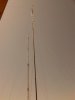
I mounted the antennas the way it was explained, and managed to run the system with only 12 watts of reflected power while the forward power is 1020 watts. I modified ronsimpson drawing a little to gain more height(Will post a photo soon). The telescopic mast is now at 25 meters. I will hopefully take it to its maximum of 34 meters.

After I'm done, range will hopefully increase to some decent km (~ 50 km). Wish me good luck.

Again, thanks go to Nigel, ronsimpson, and everybody else who helped me. I'm really grateful and happy with the new knowledge I gained
 
This is the diagram:
 

Attachments

  • Image2.jpg
    Image2.jpg
    19.5 KB · Views: 279
GOOD JOB SRAM! 1kwatt!!!! I think you antenna has a gain of about 4.
What are you transmitting? Music (rock/classic), talk?
It would be fun to come and see you. (but too much work)
 
I broadcast music/talks/some lessons and some drama series.

This is a shot from the RF Amplifier I'm using:
 

Attachments

  • RF power Amplifier.jpg
    RF power Amplifier.jpg
    61.3 KB · Views: 282
Couple of questions :

I know that the more the gain the antenna is, the more directional it is. Now, the solution I was given is supposed to radiate power into all directions horizontally. Also stacking antennas vertically like I did is supposed to increase the overall gain, right? So how can these two sentences play out together? Is it reducing power radiated up and down and increasing horizontally in all directions(North, South, East, West) ?

And regarding ERP, is that the number I see in my amplifier? Is that the effective radiated power? In my case is ~1000 watts like you could see in the photo above?

And, the photo above, is it an indication that the overall system is in a healthy state and running optimally since almost no power is being reflected ?

Few more questions:

I'd like to use the curves published by FCC to predict my range, but they require you to enter the field strength value in dbu. I read it about it a little, but still don't know the typical value that will allow typical car radios to successfully receive the signal.....so what should I put for field strength ?

And from where should I measure my antenna height? From the bottom element or the top one?

Okay last question....range can't be really predicted I know, but what should I really hope for? And given my antenna, Tx power, and the height of ~30 meters, what range value that will make me think I'm doing something wrong? In other words, what range shouldn't be acceptable by me?
 
>I do not know what ERP on you transmitter is. For the transmitter to know ERP it must know what the antenna gain is. Maybe there is a place to enter the gain. I think your ERP is about 4000 if you are sending 1kW at the antenna. There is some loss in the coax.
>I think the antenna height is measured from the center of the antenna. Not center of tower.
>The first picture is of an antenna with one element. It shows almost the same power N,S,E and W. You antenna is not that good. I think you antenna is -3db on the back side and 0db the other 3 directions.
>Vertically there is 1X power at 0. Up/Down (90) there is 0 power. At 30 there is almost full power. At 60 there is about 1/2 power. No people live at +60. The people at -60 do not want that much power.
>Picture 2 is from a book.
>Picture 3 I changed so it can be understood. You can now see with more elements the power at (0) is greater! The power at 60 and 30 goes down with more elements.
 

Attachments

  • antenna 1.jpg
    antenna 1.jpg
    138.8 KB · Views: 257
  • antenna 4.jpg
    antenna 4.jpg
    13.3 KB · Views: 248
  • antenna 4b.JPG
    antenna 4b.JPG
    24.1 KB · Views: 263
Take it easy on me ron! And you need to define your digits! I know some are angles. Are all of them angles? And the radiation pattern, is it like looking at the antenna from above? or from the side?

I will come back...need to go now(I'll also post pics of the actual installation so that you can see).
 
Click on the pictures to make them big.
I am using the numbers, angles, from the first picture.
The graph that shows the same power from all angles, 0 through 360 is looking down on the antenna.
The picture that shows power at 0 and 180 and no power at 90 is viewed from the side.

The picture from the book (2) I do not like so I rotated the picture (3) and stretched two of the graphs to make then to scale.
 
Okay ....but what do you mean by saying my antenna is not that good? Why?

You antenna is not that good. I think you antenna is -3db on the back side and 0db the other 3 directions.
 
I can not find the data for your antenna today. I think your pattern is "round" for 3/4 of the circle. The back side of the antenna sends out less power. On the other post I recommended the mast should point in a direction where less people live.

This picture I added a black dot for the antenna and a dot for the mast. The new red line is the radiation pattern. There is one direction where the power is less.
 

Attachments

  • antenna 5.JPG
    antenna 5.JPG
    8.1 KB · Views: 244
I'm reading about radiation patterns to fully understand your comments. But for the time being, can you answer this for me. If I want to concentrate the signal in the southern west direction, how should my array look like? You can take a look at the photo below.

Also, can you recommend me a really sensitive little digital radio to test my range with? I won't be using a car.
 

Attachments

  • IMG-20110906-00117.jpg
    IMG-20110906-00117.jpg
    203.8 KB · Views: 249
ronsimpson, sounds like you are busy. Anyways, the station did 75 Km! Better than what I hoped for. Again, I'm grateful to all of you guys. Thanks.

Further comments are welcomed.
 
Status
Not open for further replies.

Latest threads

New Articles From Microcontroller Tips

Back
Top