joe_rocket
New Member
I'm new to electronics and searching google I found this forum.
I am wanting to build a two part system that will have two out puts, one input.
the system is a 12v dc auto system
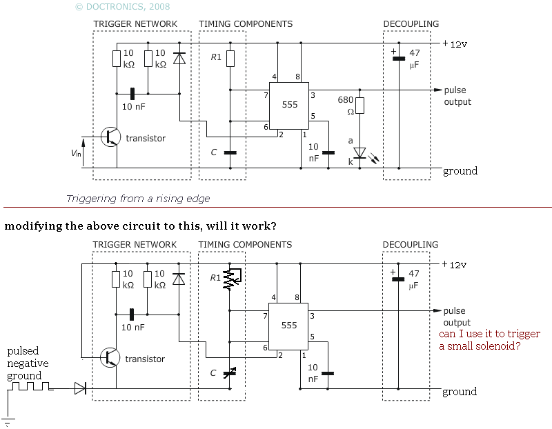
the input side will be a pulsed ground, up to 5000 pulses per minute.
from that i'd like to do these two things.
for one I'd like to have a knob that will adjust the system using a variable capacitor?
it will measure the pulse rate, and if the pulse rate is to high it will trip the output to ground.
the second I'd like to do is have the same basic setup, using a knob (again a variable capacitor?)
that would set the output. I want the system to take the pulsed ground signal and also send out a pulsed ground, but vary the output by the pulse duration (maintaining a constant pulse rate), the lower the input rate the lower the output pulse duration, the greater the input pulse rate the greater the output pulse duration (0-100% going from 0 pulse per minute to 5000 pulse per minute, but having an amount of adjustment using a knob).
are these things that would be easy to build? It would seem so but I'm new to this and looking for new learning projects. any help would be greatly appreciated.
again, I'm new but have a basic understanding of ac/dc, capacitors, diodes, resistors etc...
I am wanting to build a two part system that will have two out puts, one input.
the system is a 12v dc auto system
the input side will be a pulsed ground, up to 5000 pulses per minute.
from that i'd like to do these two things.
for one I'd like to have a knob that will adjust the system using a variable capacitor?
it will measure the pulse rate, and if the pulse rate is to high it will trip the output to ground.
the second I'd like to do is have the same basic setup, using a knob (again a variable capacitor?)
that would set the output. I want the system to take the pulsed ground signal and also send out a pulsed ground, but vary the output by the pulse duration (maintaining a constant pulse rate), the lower the input rate the lower the output pulse duration, the greater the input pulse rate the greater the output pulse duration (0-100% going from 0 pulse per minute to 5000 pulse per minute, but having an amount of adjustment using a knob).
are these things that would be easy to build? It would seem so but I'm new to this and looking for new learning projects. any help would be greatly appreciated.
again, I'm new but have a basic understanding of ac/dc, capacitors, diodes, resistors etc...
Last edited: