Continue to Site

Welcome to our site!

Electro Tech is an online community (with over 170,000 members) who enjoy talking about and building electronic circuits, projects and gadgets. To participate you need to register. Registration is free. Click here to register now.

  • Welcome to our site! Electro Tech is an online community (with over 170,000 members) who enjoy talking about and building electronic circuits, projects and gadgets. To participate you need to register. Registration is free. Click here to register now.

Newbie - Momentary make & break a circuit on relay activation

Status
Not open for further replies.

JeffT

New Member
Hi

I'm completely new to this so sorry if I use the wrong terminology. I have made a light / dark switch from a kit which activates a relay, (just soldering the components in the correct location, I know, but it works which is a big step for me.)

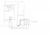
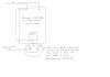
Now I want to control an existing motor which requires just a momentary make and break of a circuit to activate it. This needs to activate just once when the relay activates and again when it deactivates. The motor has its own internal control to turn it off.

I've found here and elsewhere lots of references to a make / break switches which activate a circuit continuously until the next make / break switch press. I really need to do the opposite.

The supply to the light / dark switch is 6.0v and the circuit which needs a momentary connection is 4.5v.

I've ben considering using a latching relay which would effectively deactivate itself after receiving a supply from the relay in the light / dark switch, the other side of the relay could do the make / break of the motor control circuit. This would again activate when the light dark relay deactivated. However I can only find a 12v DP latching relay, and it also seems poor to use one relay to control another, there must be a more eligant solution.

I've also tried a 555 timer which gives a short pulse but this also needs a make / break switch to stop the output. I seem to be chasing my tail getting ever more complicated when I guess there is probably something simple out there I don't know about

Hopefully somebody can help

Regards

Jeff
 
Hi Jeff...

I think it might be useful if you described what the application is a little better, and perhaps posted a simple schematic (or diagram) of the intended function of this circuit. I read this and some of it seems contradictory.. I know that wasn't your intention but that's how it's coming over!

I did get SOME idea of what you need, and it seems like a fairly simple problem to solve.

Have a go at a diagram of some sort as I suggest (scanned drawing or photoshopped). That would be helpful, I'm sure you'd get more feedback (from me or someone else!).

-CF
 
Thanks for the reply CF

I've sketched out what I need to do on the attached Light Dark relay.JPG attachment (2nd thumbnail). In principle it is very simple. If the relay on the light / dark switch just made and broke the circuit as the sky got lighter all would be well, but it would need to go to a mid point not connecting the Dark side of the relay until the light level started falling again and the relay deactivated. This would also need to be a momentary contact returning almost immediately back to a neutral point.

I also attach my sketch Light Dark relay initial idea (1st thumbnail), a highly theoretical way of possibly using a latching relay to achieve this. However the latching relay would be controling itself so would need something to hold enough charge (a capacitor?) to keep the latching relay coil energised long enough to switch itself off. I'm not sure if this is possible.

In this example the main light / dark relay allows a current to pass throught one side of the latching relay to the motor. The current here connected through a transistor allows the circuit controlling the latching relay to pass a current. This activates the latching relay coil which therefore disconnects the controlling circuit and thereby the the circuit to the motor. When the light falls the light / dark relay switches sides and the Motor control circuit & latching relay are re-energised therefore again switching itself off again after the motor control circuit has a momentary contact.

That's about it. The first sketch & paragraph are probably simplest as it says what I am trying to achieve. The second is one way I was trying to acheive it. I also tried a timer circuit but that'd confuse matters even more.

Hope this helps. The circuit is to control the curtain closer which I've had for 20 years. The existing sensor has failed. I could try repairing that but I thought I'd have a go at something myself. The system is obsolete.


Regards

Jeff T
 

Attachments

  • Light Dark relay initial idea.JPG
    Light Dark relay initial idea.JPG
    822.9 KB · Views: 436
  • Light Dark relay.JPG
    Light Dark relay.JPG
    799.2 KB · Views: 319
So, if I got this right: the idea is that when it gets dark, the curtains close? And the relay that controls the motor needs a short pulse?

If that's right: you will maybe have a hysterisis problem. That is to say, when it's starting to get dark, light levels could fluctuate (as they could when clouds pass overhead for example). So, you might find that the relay will at some point in the day click repeatedly.

What you need, I think, is a system that (when it gets dark enough) gives a short output pulse to operate the curtain motor, and then will not operate again for some fixed time period (e.g., 1 hour).

Am I right? If not - please clarify. If I am - the Velleman board clearly won't function correctly - but you know that already, I guess.

-CF
 
CF

I'm not sure how the motor is controlled internally but just connecting the 2 wires together momentarily starts its operation. It stops when the motor won't move any more, it probably has a voltage or resistance sensor in it. Whatever controls it, reverses the operation for the next momentary contact when the light passes through the predetermined level.

The Velleman kit has a delay to stop false operation on fluctuating light levels. I imagine this is changable by changing some of the components if the delay isn't long enough. If not I could probably add a timer in the circuit. I've already made a working 555 timer circuit on a breadboard which seemed remarkably simple.

Essentially you are correct, when the light level falls I want a momentary contact (at an adjustable light level) which only operates once. It will then operate again momentarily as the light levels rise.

Hysterisis, a term I've not heard for about 40 years since school. I definitely want to avoid the 'flickering' as the light level nears the preset level. I'm sure a I read somewhere that there is some sort of transistor or FET or something that once it switches on it stays on, and a darlington pair makes for a much better switching action.

Regards

Jeff
 
Jeff,

I assume from your reference to Velleman that you are using their light detector circuit kit. Almost all of their relay outputs have SPDT contacts. If I'm correct so far, you need an "edge detector" that reacts to change of the relay state. In this circuit, the relay on the left is in the light detector. With that, a capacitor, and a small reed relay you will have a set of contacts that momentarily close when your detector relay switches. The ON-time of the reed relay depend on its coil resistance and the value of the capacitor.

Ken
 

Attachments

  • Relay Edge Detector.gif
    Relay Edge Detector.gif
    3.3 KB · Views: 512
Jeff,

I assume from your reference to Velleman that you are using their light detector circuit kit. Almost all of their relay outputs have SPDT contacts. If I'm correct so far, you need an "edge detector" that reacts to change of the relay state. In this circuit, the relay on the left is in the light detector. With that, a capacitor, and a small reed relay you will have a set of contacts that momentarily close when your detector relay switches. The ON-time of the reed relay depend on its coil resistance and the value of the capacitor.

Ken

That seems like a nice, elegant and simple solution. I was about to suggest cascaded 555 timers. The only problem I could see with this (relay circuit) is if the Velleman light detector is not well-behaved, but since I don't know anything about that I can't really comment...
 
Last edited:
Hi Ken

I'm not too good at this, but from the circuit it looks like when the light detector relay switches to NC the capacitor is charged and I presume this somehow mometarily activates the Reed relay. Does this circuit again activate the reed relay when the light sensor relay switches to NO? I presume the capacitor then discharges?.

If that is true it'll do exactly what I want. I'll read up on reed relays.

No worries about Velleman. If that does misbehave I'll try some other circuits I've seen. I just bought that as it seemed a good place to start.

Thanks

Jeff
 
That's right.

I used a reed relay, but only because they're very small. You can do this with almost any DC relay. However, there are some DC relays that have a flyback diode built in, across the coil. These would not work.

Ken
 
Thanks Ken

Time to study the parts catalogue. If it works which I'm sure it will, it'll be great, I knew there must be a simple solution.

Jeff
 
Status
Not open for further replies.

Latest threads

New Articles From Microcontroller Tips

Back
Top