Continue to Site

Welcome to our site!

Electro Tech is an online community (with over 170,000 members) who enjoy talking about and building electronic circuits, projects and gadgets. To participate you need to register. Registration is free. Click here to register now.

  • Welcome to our site! Electro Tech is an online community (with over 170,000 members) who enjoy talking about and building electronic circuits, projects and gadgets. To participate you need to register. Registration is free. Click here to register now.

Newbe needs help with crazy project

Status
Not open for further replies.

Angelfci

New Member
Hi there!
I am new to the board and excited for some help to turn my vision into reality! Please forgive my lack of knowledge of all things electronic but I am sure experts here can help me.
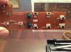
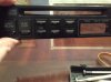
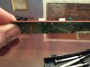
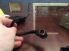
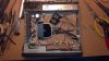
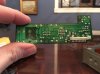
I took a CD player from my 21 yr old miata and would like to add a bluetooth hack to it. But keeping the Cd player looking as stock as possible. First I gutted the interior of CD player. I need to add an on/off switch to to the front panel to turn on the bluetooth receiver that will sit inside the CD. The front panel has built in buttons see picture. The PCB panel has switches for the buttons. See picture. I think those switches are just momentary. Example the FF and REV, each has a switch behind the face plate. I took a sideways picture of the board showing each switch is conneected using two soldered posts. Is there a way to turn these two (FF and REV) into an on/off switch? Can I solder something to the back of these existing buttons? The other solution would be to forget about the existing board and adapt a push button on/off switch behind either the FF or REV and then just push on and then push the same one again for off. I thank you and appreciate your help.
Angel
 

Attachments

  • image.jpg
    image.jpg
    971.6 KB · Views: 181
  • image.jpg
    image.jpg
    919.1 KB · Views: 195
  • image.jpg
    image.jpg
    908.9 KB · Views: 174
HI, Welcome!
In regards to the question, it would be easy to hack the buttons, just disconnect them at any point in the node, then solder your conn in,

however , if there are other buttons running off that node you will also need to not only cut them out as well, but you will need to add a bypass wire connecting them back up , outside of your button circuit
in the back of board image , we cannot see the nodes (the pcb connections), so cannot specify exactly what to do.....

...also adding a flip-flop chip will remember which button you pushed last .. if bluetooth can't do that on its own....

I fear thou that is the easy part, i wonder how you are going to tie bluetooth in to radio, and what is the bluetooth going to be doing? is this prebuilt, ...ect
 
There are quite a few bluetooth audio adapters available that give a line level stereo audio output. I use one to feed streaming audio from my smartphone to my stone-age home audio system. They're tiny, so there should be no problem fitting one into the space vacated by the CD player, and then do some minor surgery to adapt the buttons.
 
I fear thou that is the easy part, i wonder how you are going to tie bluetooth in to radio, and what is the bluetooth going to be doing? is this prebuilt, ...ect[/QUOTE]

Thanks for the reply!
It is actually easy to get the input into the radio. The factory radio has a 13 pin din plug for the factory CD player. I purchased a spare factory cd player and removed the plug. See picture. I have a map to all the wires and pin locations. Attached is a picture from another site of a bluetooth hack similiar to the one I want to do, although I am now leaning towards Airplay. There are a few videos on youtube showing how to do it. I have also attached a picture and marked the button connections of the back of the pcb board so you can see the connections. I really dont know what to do to use the buttons as a switch. Please explain it to me step by step as well as give me any part numbers for things I need to order. I need the FF button when pressed to turn on and stay on until the REV button is pressed and then I want it off. I can solder directly to the buttons on the pcb board. To the experts it must seem really easy but to me this is like. Another language I am trying to learn. Thank you again for the warm reception and advice!
 

Attachments

  • image.jpg
    image.jpg
    701.2 KB · Views: 159
  • image.jpeg
    image.jpeg
    304.3 KB · Views: 146
  • image.jpg
    image.jpg
    900.1 KB · Views: 162
little mistake there, Instead of flip flop we should use a " 2-coil-latching relay", I am guessing that your Bluetooth device will run at 12v car power, when selecting relay we need to know the current/power of your device but most likely 1 amp is more than enough.

k, so:
1)the red is where you need to cut at 6 points, make sure cut shows infinity ohms(ask!)
2) the blue you need to add wire to get other buttons working again
3) yellow wires are what you need to add, wires do not connect together unless there is a round yellow dot!!!!
4)green wire you need to add, is just green so we can see it better, but again only connect at green/yellow dot!

Image3.jpg

for wire i would use phone wire at smallest, i would cut about 3-4inch long, strip all tips about 0.5cm give or take (after step 1&2) solder up relay , then test which pins which, and solder in to stereo as i go
 
Last edited:
THAT IS FANTASTIC! THANK YOU!
Do you have a source for the 2 coil latching relay? Yes power is 12volt that would normally come from the cigarette lighter.
Thank you very much! This is exactly what I need.
 
Last edited:
Status
Not open for further replies.

Latest threads

New Articles From Microcontroller Tips

Back
Top