Continue to Site

Welcome to our site!

Electro Tech is an online community (with over 170,000 members) who enjoy talking about and building electronic circuits, projects and gadgets. To participate you need to register. Registration is free. Click here to register now.

  • Welcome to our site! Electro Tech is an online community (with over 170,000 members) who enjoy talking about and building electronic circuits, projects and gadgets. To participate you need to register. Registration is free. Click here to register now.

New Question about old Circuit ?

Status
Not open for further replies.

gary350

Well-Known Member
Am I correct in assuming if I double the cycle time of this circuit from 4 seconds to 8 seconds it will double the life of the battery.?

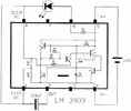
This circuit flashes about, on 1 sec, off 1 sec, on 1 sec, off 1 sec.

If I change resistor R4 & R5 from 47K to 200K then circuit be on, 1 sec, off 3 sec, on 1 sec, off 3 sec.

I have already changed R3 & R6 from 470 ohm to 1000 ohms and get an unexpected surprise. Instead of each LED blinking for 1 sec now the LEDs stay on for 2 seconds. Apparently 1000 ohms makes the capacitor discharge slower. I have not yet tested to see if LED brightness has changed it needs to be visible from 250 ft away.

4 Eveready batteries are

$22.00 at Target
$20 at Kroger Grocery store.
$18 at Walmart

I am tired of changing batteries. Dollar store batteries were lasting 1 year but not anymore they are out dated when I buy new batteries. It would be great to get, 2, 3 or 4 years with better batteries.

I have not tested the voltage of 2 Eveready batteries in series yet. When volts drops to 2.7v circuit will not run.

100_3266.JPG


100_3267.JPG


100_3265.JPG
 
Last edited:
Male sure you have high bright leds which produce more light
for a given current.

If you sim circuit you can see where the power is being consumed, if I get
a chance I will take a look at it tomorrow.

The Pdiss in the 100 uF also could be looked at -

1640745212434.png


Another way of doing this is to use an ATTINY85 and put it to sleep periodically.


Regards, Dana.
 
"Am I correct in assuming if I double the cycle time of this circuit from 4 seconds to 8 seconds it will double the life of the battery.?"

No.

There are two LEDS that are mutually exclusive; whenever one is on, the other is off. That means that an LED is on 100% of the time, no matter what the flash frequency.

Also, if you keep the functionally-paired components the same value, then as you change the component values the frequency will change but the duty cycle still will be 50%. This applies to R4-R5, R3-R6, and Cx and Cy (the 100 uF capacitors).

If you make R4 and R5 or Cx and Cy unequal, the duty cycle will change; one LED will be on longer than the other.

ak
 
Last edited:
Sim shows majority of power goes to LED and its current limiting R.

Rest of circuit ~ < 1/10 the above.

1640783307685.png


If I remove D2 and change R3 to 5K I get about 7-8 mW consumption, versus 2 led
approach averaging ~ 17 mW. But I also get an oscillation in Q1 at high freq which would
have to be addressed. Note this means you would not get alternating red / yellow flashing.

Key is high efficiency LED(s) I think, and run them at lower current.

Note P dissipated in 100 uF ~ 1 mW, not a key problem.

You could also think about using a 18650 LiO battery, industry standard. You would have to compare mah
to same V discharge V to see if that as a solution better.


Are you using 4 batteries as series/parallel, eg. two sets of two in parallel and
then the two sets series-ed ? You mention 4 batteries ......Or just using two in series ?
C Cells ?

Lastly if you do a pwm method of driving with a small controller you can take advantage of
persistence of vision to allow LED to be off longer using less power, when its on.....twist on words :)


Regards, Dana.
 
Last edited:
Sim shows majority of power goes to LED and its current limiting R.

Rest of circuit ~ < 1/10 the above.

View attachment 135377

If I remove D2 and change R3 to 5K I get about 7-8 mW consumption, versus 2 led
approach averaging ~ 17 mW. But I also get an oscillation in Q1 at high freq which would
have to be addressed. Note this means you would not get alternating red / yellow flashing.

Key is high efficiency LED(s) I think, and run them at lower current.

Note P dissipated in 100 uF ~ 1 mW, not a key problem.

You could also think about using a 18650 LiO battery, industry standard. You would have to compare mah
to same V discharge V to see if that as a solution better.


Are you using 4 batteries as series/parallel, eg. two sets of two in parallel and
then the two sets series-ed ? You mention 4 batteries ......Or just using two in series ?
C Cells ?

Lastly if you do a pwm method of driving with a small controller you can take advantage of
persistence of vision to allow LED to be off longer using less power, when its on.....twist on words :)


Regards, Dana.

I have 2 batteries in series = 3.22 volts. When voltage drops to 2.7v the circuit stops running. In the past this circuit runs for 1 year but Dollar Tree batteries are junk they are 2 years old already on the store shelf most are very low voltage when I remove them from the package. Junk battery no longer work for 1 year now they only last 1 month.

The original circuit had smaller caps I think 20uf LEDs flash so fast an not very bright they can not be seen from 100 ft away. 50uf cap was brighter. 100uf cap Red LED can be seen 250 ft away. I only need the RED LED the yellow is only needs to make the circuit run.

I experimented with my bread board set up now I remember why I used RED and YELLOW LEDs, 1 LED is always ON, at 250 ft yellow can not be seen it looks like 1 red LED flashing. The other reason I used this circuit is, battery life is 12 months other circuits are 6 or 3 months.

I need a better 1 LED circuit that will run on 3v or 1.5v.

100_3271.JPG
 
Last edited:
This works at 2.5 V, but sim has to be verified by benchtop work.

1640807315654.png


Note R5, 100 ohm, sim, showed Q1 oscillating heavily at high freq, I think because
it stayed in active region too long versus acting as a switch. So put it close to base
of Q1.

Overall power level ~ 1/4 what it was prior. At 2V the sim still seems to indicate monostable
still working, but power level in the LED quite low. You could lower R4 to correct, but that
means when batteries are fresh current much higher in diode, if its threshold low enough.
Try it out on the bench.

Regards, Dana.
 
Last edited:
Gary, you said that 4 Eveready batteries cost $18 at Walmart but Eveready batteries are not made as a D size anymore.
8 Energizer alkaline D cells cost $15.37 and 12 cost $17.76 at Walmart.com.

Have you tried using a flashing LED that when it turns on it can turn off a transistor and another LED? no capacitors are needed.
 
This works at 2.5 V, but sim has to be verified by benchtop work.

View attachment 135379

Note R5, 100 ohm, sim, showed Q1 oscillating heavily at high freq, I think because
it stayed in active region too long versus acting as a switch. So put it close to base
of Q1.

Overall power level ~ 1/4 what it was prior. At 2V the sim still seems to indicate monostable
still working, but power level in the LED quite low. You could lower R4 to correct, but that
means when batteries are fresh current much higher in diode, if its threshold low enough.
Try it out on the bench.

Regards, Dana.


Your circuit works. I had no 5K so I used 4.7K. I had a 100 ohm resistor ready and a jumper wire ready for the 470 ohm resistor. With the circuit running I replaced the LED with the 4.7K resistor and it started flashing the LED before I added the 100 ohm resistor or the jumper wire. LED is ON 2 seconds and OFF 3 seconds.

100_3273.JPG
 
Last edited:
Gary, you said that 4 Eveready batteries cost $18 at Walmart but Eveready batteries are not made as a D size anymore.
8 Energizer alkaline D cells cost $15.37 and 12 cost $17.76 at Walmart.com.

Have you tried using a flashing LED that when it turns on it can turn off a transistor and another LED? no capacitors are needed.

YES here is the photo. I paid $18.30 for 4 Energizer batteries. I went to several stores most prices were higher than Walmart. Wife buys at Walmart.com I have her look at prices tonight. I already used 2 batteries in a circuit don't have all 4 to take photo of.

Wife found D-12 Energizer 12 pack batteries $21.96 at Walmart $6 postage;

She found D-12 Energizer 12 pack batteries $17.72 at Amazon free postage.

100_3265.JPG
 
Last edited:
If you put heatshrink band around two batteries and heat the edges first,
then the middle, that will pull the two batteries together firmly so contact
is always solid.


Regards, Dana.
 
I tired doing this a different way. Using an ATTINY85 to directly drive the two LEDs
with a PWM. Keeping in mind human eye has persistence could I reduce duty cycle,
hence average current needed from battery, by doing a low duty cycle drive of LEDs.

So here we have upper traces, drive to 1 LED, its connected PWM pin >> LED >> pin
to ground to turn on LED.

So blue trace is PWM output, running at 1/16 duty cycle.

Datasheet says I will get ~ 40 ma out of pin when high sourcing current, so 1/16 duty cycle
= ~ 2.5 mA average being supplied from battery. I have not yet tried a lower duty cycle, like
1/64.

So one would either make measurements of integrated brightness or subjective observation
and play with duty cycle to take advantage of eye persistence property. Which cuts power
needed.

1640872287440.png


Video, note Iphone seems to suppress RED, these are two LEDs connected to ATTINY85, one red,
one yellow. Video attached.

I used mBlock to create program code -

1640873541079.png


You drag functional blocks onto canvas on right, config, like set pin numbers associated with PWM, LEDs,
and hit upload. It generates the Arduino code which you program into ATTINY85 in this case. If you are
not a coder this is not a bad way of starting, and you can see C like code mBlock generates for the pro-
cessor. Kids in 6'th grade doing this to program simple robots.

Another vehicle to see if design can be improved.

Note the curves of source current out of a pin on ATTINY85 are typical, not maxes. So I am thinking
to insure pin max allowed current in datasheet not exceeded maybe add a diode in series with LED
to move up and to the left of this graph pin current for ATTINY85.

1640874009350.png


I did not add the A to D blocks to handle the daylight sensor, thats trivial to do, ATTINY85 will handle that as well.

So solution is 8 pin ATTINY85, 2 LEDs, 2 diodes, daylight sensor, and a R to use with it to set V divider.


Regards, Dana.
 

Attachments

  • IMG_0411.zip
    9.1 MB · Views: 205
Last edited:
The blinking LED circuits I have made (CD4017 chasers) show that a light duration less than 30ms appears dimmed.
 
I did testing and this circuit this is what I got. Circuit does not have to be 50/50 duty cycle.

C1 is the OFF capacitor. 100uf = 3 second, 200 uf = 6 seconds

C2 is the ON capacitor, 47uf = 1 second, 100uf = 2 seconds.

100_3276.JPG
 
Since the value of the left transistor's collector resistor is increased then the 47k base resistor value for this transistor can be increased and its timing capacitor value can be decreased for the same timing but less wasted battery current.
 
The blinking LED circuits I have made (CD4017 chasers) show that a light duration less than 30ms appears dimmed.
The video I posted shows fairly good brightness with PWM at 1 mS period, 60 uS LED on time.

That setting just a starting point for experimentation.


Regards, Dana.
 
Try the change audioguru suggests but sim seems to indicate most of
the power used by LED and R4, its current limiting R.

So maybe you can get another 1/2 mW by fiddling....


1640894808377.png


Regards, Dana.
 
Here is another "pld ckt" solution. Doesnt get much simpler than this and only needs one 1.5V cell.
The 3909 has been in so many of my flashing ckts, unbeatable battery life & simplicity.
If you need alternating LEDs, trigger a second 3909 chip.
Add solar cell to disable in daytime if you want, but the battery life is so olong it may not really matter if you let it runn 24hrs.----2.6 YEARS on a D cell !!!
Cheers
Bob
 

Attachments

  • lm3909-1-5V LED Fasher circuit.jpg
    lm3909-1-5V LED Fasher circuit.jpg
    47.2 KB · Views: 205
  • lm3909 LED flshr x.png
    lm3909 LED flshr x.png
    78.4 KB · Views: 204
Last edited:
Here is another "pld ckt" solution. Doesnt get much simpler than this and only needs one 1.5V cell.
The 3909 has been in so many of my flashing ckts, unbeatable battery life & simplicity.
If you need alternating LEDs, trigger a second 3909 chip.
Add solar cell to disable in daytime if you want, but the battery life is so olong it may not really matter if you let it runn 24hrs.----2.6 YEARS on a D cell !!!
Cheers
Bob
I made a circuit with these around 35 years ago to flash LEDs at my school to signal office statuses. I was 15 at the time. I came back 7 or 8 years later to service a PC of theirs and they were still working and running on their original batteries !
 
Last edited:
Status
Not open for further replies.

Latest threads

Back
Top