Continue to Site

Welcome to our site!

Electro Tech is an online community (with over 170,000 members) who enjoy talking about and building electronic circuits, projects and gadgets. To participate you need to register. Registration is free. Click here to register now.

  • Welcome to our site! Electro Tech is an online community (with over 170,000 members) who enjoy talking about and building electronic circuits, projects and gadgets. To participate you need to register. Registration is free. Click here to register now.

New Induction heater circuit

Status
Not open for further replies.

gary350

Well-Known Member
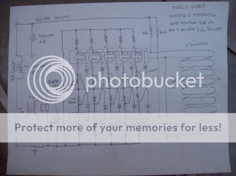
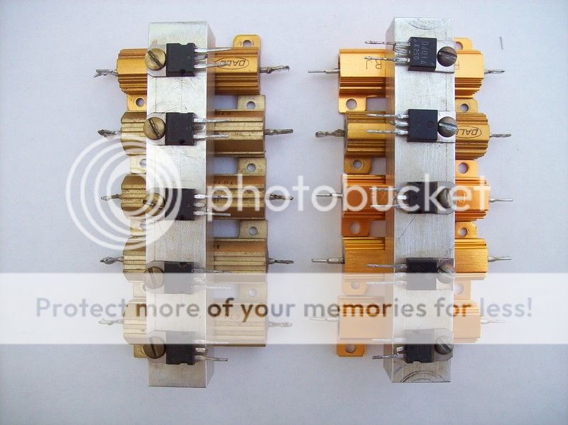
My original circuit was 2 mosfets running on 22 VDC 36 amps. The new circuit used 10 mosfets 5 in parallel on each side. There will be a 1 ohm 50 watt resistor on each mosfet to limit through each mosfet to 22 amps. The aluminum blocks are drilled through taped 1/8 npt on both ends for cooling. Cooling liquid will be high voltage transformer oil. The LC coil size has not been determined yet the plan is 2" diameter with enough turns to limit total current in the circuit to about 65 amps for now. I am going to hook up 2 mosfets at a time once I have it running on 2 then add 2 more the 2 more and so on. 5 mosfets per side is over kill just to keep current lower in each mosfet. The 1 ohm resistors are safety to limit current to prevent a chain reaction just incase 1 mosfet burns up or shorts out. I might only hook up 6 mosfets total for now the transformer is only 68 amps. The gate circuit has its own transformers and power supply circuit so it should not be effected by what the other power supply circuit is doing. The power resistors will have cooling too and so will all 8 power supply 250 amp diodes. I have some 1 ohm and 2 ohm 800 watt resistors i can use for protection to get this circuit going then remove them later. I see I made a mistake on the 22 volt power supply there is no rectifier in the drawing. Give me some help have I made any mistakes?

100_1466_zpsco62nyrm.jpg


100_1464_zpshohj18id.jpg
 
Last edited:
Are you saying about the cooling that it is running through the block you mounted the mosfets on then through the coil? Is that a good idea? the heat from the coil will be transferred into the mosfets. And water is much better at transferring heat out of something. Don't most induction heaters use total loss water for cooling? Or it is sent through a cooling tower of some sort, if not total loss.

To keep the mosfets from "running away", the usual scheme is to put resistor on the source. The gate resistors are to prevent 'ringing' when switching on and off.

Why use a bunch of small mosfets? There are mosfets made for things like this in an "iso-top" package. Or IGBT modules both are cheap if you look on Ebay. I bought some for my EDM machine and didn't pay all that much.
 
You should be able to make this with 2 Mosfets or possibly 4.
Definitely not 10.
There are many Mosfets rated at over 80 Amps.
 
Looks like you're still trying to do things the hard way. :(

Two 600 volt 600 amp IGBT bricks and a big heatsink would save you a load of money, work and components in designing and testing these induction heater designs of yours.
 
I just happen to have 20 of these mosfets. I think your right total loss water would be better. I like the idea of indestructible IGBTs I will do that soon. This project is a learning project before I do the IGBTs. This project is not costing me a dime I already have every thing to build this.
 
gary350
Maybe you could answer a couple of questions:
What is the ripple current rating of the 7400Ufd filter caps.
What is the current rating of the 8 uh inductors.
What is the length of the heating coil or it's inductance?
Then I think just some drawing stuff:
The caps across the heating coil = .47 ufd X 10 or .047 ufd.???
The gate resistors are marked 1 ohm. S/B 270??
 
I enjoy reading about your exploits. It's fascinating how simple the concept is. You are going to have a humungous inductor though. What core and wire are you using for the inductor/inductors?
 
I smell smoke and hear mosfets popping like firecrackers already. :eek:

I'm going to predict that the large 1 ohm wire wound core resistors on the mosfets outputs are going to cause a load of problems with both efficiency and the circuits overall ability to achieve any stable form of resonance due to the devices not being able to switch in a quick linear mode like they need to to stay inside the SOA limits and keep from burning up.

Just my guess at this time.


All this information is good. I will experiment with the original circuit 2 mosfets with 1 ohm resistors to see what happens. This is a good learning experience for me. My original circuit had a .2 ohm resistor between power supply and mosfet circuit for protection until I finally got it right. I need to learn if what you say is right before I continue building. Looks like everything will be on hold until after the holiday.
 
The diode 1N5819 has maximum average current 1A.
With 1ohm gate resistor the current is about 6A.
If you reduce the current to less than 1A, the ripple on the gate voltage is about 8V.
You need a bigger cap on the 12V, about 47000uF
 
gary350
Bad news. :arghh:
The circuit is a little fussy. There is not a lot of gate drive, so infact putting more FETs in parallel actually makes the hotter because they switch so slow.
The FET you have now is only rated for 55 volts, but due to the resonant circuit it has more like 65 volts across it.
The same is true of the gate diodes. 40 volt diodes with 53 volts across them.
I would make the inductors larger so there current could be lower. It is bad news when they saturate.
The one ohm resistors in the emitter is not a good idea. Think about it -- as the gate goes to 12 volts the FET starts to turn on, but as it draws current the emitter goes positive and it starts to turn off. It will end up somewhere half on and half off and be really hot.
I know you are like the guy on tool time - always looking for "more power". If so build one just like the one MaxHeadRoom78 posted with higher voltage.
 

Attachments

  • induction.png
    induction.png
    173.1 KB · Views: 376
Status
Not open for further replies.

Latest threads

Back
Top