TheRealStark
New Member
Hello,
I'm new to this forum, and am a newcomer to creating custom electronics projects.
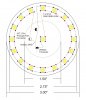
I am in need of someone to make an Eagle schematic and PCB layout that matches what I've drawn in the attached image.
Essentially, I want a ring of SMD LEDs around the circumference, and one in the center. However, I want to be able to control each part separately, which is why I'm using the two transistors. All LEDs will be powered by a 3.7V, and the center pin of the transistors will be switched by an Arduino. Also, the transistors can be placed anywhere inside the 1.5" diameter circle, and I'd prefer if they could be more symmetrical (on either side of the center LED perhaps).
The JST battery connector will be soldered to the back of the PCB, but all other components will be on the front. I will also need two holes to connect wires from the Arduino pins to the transistors, and a hole to wire the grounds to the Arduino as well.
If anyone is willing to help me, it would be very much appreciated. If you need to know any other information, don't hesitate to ask.
I'm new to this forum, and am a newcomer to creating custom electronics projects.
I am in need of someone to make an Eagle schematic and PCB layout that matches what I've drawn in the attached image.
Essentially, I want a ring of SMD LEDs around the circumference, and one in the center. However, I want to be able to control each part separately, which is why I'm using the two transistors. All LEDs will be powered by a 3.7V, and the center pin of the transistors will be switched by an Arduino. Also, the transistors can be placed anywhere inside the 1.5" diameter circle, and I'd prefer if they could be more symmetrical (on either side of the center LED perhaps).
The JST battery connector will be soldered to the back of the PCB, but all other components will be on the front. I will also need two holes to connect wires from the Arduino pins to the transistors, and a hole to wire the grounds to the Arduino as well.
If anyone is willing to help me, it would be very much appreciated. If you need to know any other information, don't hesitate to ask.