Continue to Site

Welcome to our site!

Electro Tech is an online community (with over 170,000 members) who enjoy talking about and building electronic circuits, projects and gadgets. To participate you need to register. Registration is free. Click here to register now.

  • Welcome to our site! Electro Tech is an online community (with over 170,000 members) who enjoy talking about and building electronic circuits, projects and gadgets. To participate you need to register. Registration is free. Click here to register now.

Negative supply from battery

Status
Not open for further replies.

vinke

New Member
Hi everyone,
I want to get a negative regulated 5V from a single 12V battery which is already used as positive supply..
Anyone have any ideas how I can achieve that with minimum hardware?
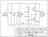
The schematic below(fromhttp://www.armory.com/~rstevew/Public/PSUs/-vgen.html) shows a way to do that but is there any easier way?
**broken link removed**
 
Last edited:
What you have does not regulate. The output is approximately –10.8 volts when the battery is 12 volts. That depends on load and battery charge.
 
Yes, it's just a simple voltage pump using a multivibrator, a bit unusual for the date on it (2000), most such circuits had used a 555 for many years previous to that.

As long as your current requirements are low, you could stick a -5V regulator on the output of it.
 
Thanks for the reply . You are right Nigel a 555 would be simpler.But something puzzling me.The oscillating signal produced by the multivibrator or 555 have voltage levels ranging from slightly less than Vcc to ground, the npn transistor is switched on by the rising edge,but what about the pnp?doesnt it require a -ve voltage less than -Vbe to be triggered on whereas the oscillating signal doesnt go below ground.
 
Nigel Goodwin said:
Sorry, you've lost me? - what NPN transistor?.

But in any case, there's no need to go outside the supply to turn on either NPN or PNP devices.
Yep sorry in the circuit, he uses two pnp transistor,but a totem pole at the output could also be used utilizing an npn and pnp transistor thats why i confusingly said npn in that case.Am I right that a pnp needs less -Vbe to be turned ON?And I am puzzled how the multivibrator provides that, if its output oscillate from +V to GRND
 
The circuit provided an voltage that oscillates between about +1V and +11V at the common point between the two output transistors. The voltage is able to source and sink current.

When it is high, C3 is charged with the transistor end positive, while D1 takes the charging current and keeps the diode end of C3 down to about 0.7V, leaving around 10V of charge on the capacitor.

When the output of the oscillator is low, there is still 10V of charge on the capacitor. It now has its transistor end at about 1V, so its diode end is down at about -9V. The diode drop of D2 means C4 gets charged to about -9V. It will take a few cycles to get there as C4 is charged from C3.

This is a standard circuit. It is like what is used in a MAX232. If you have any oscillating voltage on the positive side you can omit the oscillator and just use C3, C4, D1 and D2, as long as the oscillator can provide the current that you need.
 
vinke said:
Yep sorry in the circuit, he uses two pnp transistor,but a totem pole at the output could also be used utilizing an npn and pnp transistor thats why i confusingly said npn in that case.Am I right that a pnp needs less -Vbe to be turned ON?And I am puzzled how the multivibrator provides that, if its output oscillate from +V to GRND

It's rather crude and nasty, and doesn't make best use of the available supply, so the output will be a good way from the input voltage.
 
why not use an intersil iCL7002 or 7000? (cant remember which) all u need is a couple electrolytic caps. Plus intersil has a free sample program which is good for trying out interesting parts.
 
mike11298 said:
why not use an intersil iCL7002 or 7000? (cant remember which) all u need is a couple electrolytic caps. Plus intersil has a free sample program which is good for trying out interesting parts.

Yes,but it has to be available. I want to do it with easily available parts,i mean available in my region.
 
mike11298 said:
why not use an intersil iCL7002 or 7000? (cant remember which) all u need is a couple electrolytic caps. Plus intersil has a free sample program which is good for trying out interesting parts.
The ICL7660A is the one you're looking for I think.

I've actually got some of these ordered as samples for some stuff I'm working on that needs a +/- supply for opamps from a single +ve source.
 
The ICL7660A is perfect.

Two transistor astable multivibrators have a maximum supply voltage of about 5V as the BE junction will break down when the reverse voltage generated by the capacitors when it exceeds 5V.

If you can't get the ICL7660 then use a NE555.
supply-gif.13926
 
I want to do it with easily available parts,i mean available in my region.
And your region would be....... ? :confused:

You hopefully understand our frustration; you impose geographic constraints on us, yet you don't see fit to put your location into your User Profile. :mad:
 
Hi Vinke,

You can also try something like this, using standard components:

(note: in this example, regulated output was +6Vdc, -6Vdc, but can easily get -5Vdc by breaking the symmetry)
 

Attachments

  • ConvFuenteSimaSime.PNG
    ConvFuenteSimaSime.PNG
    44.3 KB · Views: 192
Status
Not open for further replies.

Latest threads

New Articles From Microcontroller Tips

Back
Top