Continue to Site

Welcome to our site!

Electro Tech is an online community (with over 170,000 members) who enjoy talking about and building electronic circuits, projects and gadgets. To participate you need to register. Registration is free. Click here to register now.

  • Welcome to our site! Electro Tech is an online community (with over 170,000 members) who enjoy talking about and building electronic circuits, projects and gadgets. To participate you need to register. Registration is free. Click here to register now.

neeed help reading relay diagram!!!

Status
Not open for further replies.

_bLaDe_

New Member
Hi guys stumbled across this great forum when looking for electronic discussions and i hope i can gather some good help before installing my car alarm system. Just need help reading the diagram in the picture below for the relay(s) diagrams.

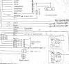
Ok what I can make out is:

Wire 86: Goes to alarm
Wire 85 & 30: Break the wire and connect each end to the circuit of fuel pump or ignition solenoid
Wire 87a: ground?


**broken link removed**

here is a picture of the relays and the diagram on the relays which includes an extra wire.

**broken link removed**

ok on another forum i was told that this could be the method of doing it but need ideas on which is right and or the wrong way:

"86 to Key On, 85 to ground, cut fuel pump wire with one end to 87 and the other to 30. This is how I see it, 30 and 87a have continuity when the coil is not energized. 30 and 87 have continuity when the coil is energized. What you want is for the coil to be energized (fuel pump active) when the key is in the "ON" position. You will not use 87a because you do not want continuity while the coil is not energized."


Some help would be appreciated!!
 
So.. Keyon is +12V when the ignition key is on ?

The wires from the relays back to what I assume is the alarm junction box.

Would they be ground returns perhaps ? Pull the control line to ground and the relay turns on when the ignition is on, if left to float the car won't be going far.

What I'm not sure about is why Keyon seems to just appear on the schematic from thin air, and what's that Trapezoid shape next to it ? Im guessing the pump is controlled by a relay before fitting the alarm ?
 
Last edited:
yes key on is 12v when ignition.
thats what im not sure about those shapes and diagrams! its confusing!! please help some on
 
For starters, it appears that they slightly misprinted their schematic as far as the polarity of the fuel pump and coil, as if it is getting a positive connection from both sides, so-to-speak. The relays are simply a circuit-interrupt, the current flows through the contacts until the alarm triggers, pulling a low (negative ground) on the coils of both relays (86). The 85 Terminals are always connected to positive when the key is on (ACC). The diode icon on the relay shows an internal diode that "clamps" the voltage that is re-induced from the coil once it is de-energized (The collapsing magnetic field remaining actually spits out a voltage spike). This protects the transistor that most likely is turning it on. Note this, as applying the wrong polarity to the coil will be a dead short across the diode. (85+, 86- is the correct way)

I would check, both with key on and off, what side, negative or positive, remains at the Fuel Pump and High Coil. You can use a multimeter with one lead to ground, then the positive battery terminal, if possible. If the negative side, for example, is normally the switched side, cut that wire and run it to your relay contacts.(30 and 87a). By simply butt splicing additional wire to these cut ends and running these leads to the relay contacts, that saves you the ordeal of figuring out which polarity (+ or -) connect to 30, as in the drawing.

The HIGH COIL relay seems to show 86 and 30 to be together (the line coming off of the coil), but I strongly believe that to be a misprint. It makes no sense. 87 Should be LEFT ALONE. This is under the assumption that the 86 line pulls to ground ONLY during an alarm condition, as most alarms I have seen. Feel free to "meter" this wire in reference to ground to verify continuity. Relays are usually only on for the shorter duration compared to long term, but it doesnt hurt to check first. If for some odd reason the 86 lead reads "Ground" full time EXCEPT during a alarm condition, then you WOULD use 87 and leave 87a ALONE.

Hope that helps!! Reply if you have another question.
 
Last edited:
You need a better Diagram. The picture is not good and cut off on both sides.

I tried to lighten it and some whires are there but the picture cuts them off.
 

Attachments

  • info2.jpg
    info2.jpg
    75.5 KB · Views: 277
  • info3.gif
    info3.gif
    149.6 KB · Views: 216
Last edited:
Status
Not open for further replies.

Latest threads

New Articles From Microcontroller Tips

Back
Top