Continue to Site

Welcome to our site!

Electro Tech is an online community (with over 170,000 members) who enjoy talking about and building electronic circuits, projects and gadgets. To participate you need to register. Registration is free. Click here to register now.

  • Welcome to our site! Electro Tech is an online community (with over 170,000 members) who enjoy talking about and building electronic circuits, projects and gadgets. To participate you need to register. Registration is free. Click here to register now.

Needing help finding a Solid State Relay

Status
Not open for further replies.

hizzo3

New Member
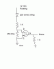
I am looking for a SSR much like a regular relay that there is 3 pins on the switch side, and just the standard 2 on the "coil" side

kinda like this

.......___
___/
.......___
(ignore the periods, couldn't remember the html code for leaving in spacing)

that way when the switch isnt active, it still has the "off" circut running. i am needing to control 2 modes (a high and low) in a lighting circut and i like the reliablity and switching speed of the SSR over a relay

Thanks
 
Last edited:
Don't know how much power you need to handle, but Clare makes some opto isolated versions.

**broken link removed**

Assuming this is for your LED tailight, the best way, by far, is to PWM the drive to the LED's for the low level, and steady DC for the full bright. Something like 60/40 on to off will be close for your needs. Playing with the duty cycle to remove any visiable flicker, my experience is anything faster than about 5mS or so, is not visible, except maybe under flourescent light.

Or, with a few extra parts, choose a buckpuck that already does this, and have two presets for brightness levels. As in put a trimmer pot set to the dim level on the buckpuck, and have a small signal ( PN100 , 2N3904 ) short it out when the brake light wire is energized.
 
Looks like you want SPDT Type, but you forgot to mention:
(1) Voltage Rating
(2) AC or DC
(3) Current rating needed.
 
hotwaterwizard said:
Looks like you want SPDT Type, but you forgot to mention:
(1) Voltage Rating
(2) AC or DC
(3) Current rating needed.


12.3-15 VDC@ 2amps is what will be running max. so what ever a good bit of overage would be, add that on (like in resistors when needing a .5 watt get a 1 watter). i looked at pwm, but i just dont have the skills yet. just to give you an idea. the only circut level building i have was with a radio shack kit i got one year. most this stuff on here i spend like 10-20 mins trying to read and research, what is a "flux capacitor :eek: " lol
 
i cant seem to find any spdt solid states, wonder if i can use 2. one of which is normally off, and the second is normally on, and when energized, they switch.
 
It seems to me you would probably be better just using a relay?, or designing your own switching circuit? - but you haven't made it very clear what you're trying to do?.
 
You will not likely find many SPDT solid state relays that can handle the kind of power you want. In the link I gave above, what you want is called "form C" which is how relay contacts are described for SPDT. Most times it is cheaper and easier to develope a circuit than use SSR's for a power application in SPDT. let us know what you want to do, and we can probably come up with a simple and solution.

I based my comments above on the sketch in your other post for the brakelight circuit, there you could simply replace the SSR with a FET or bipolar transistor.
 
I am working on an LED-luxeon replacement taillight and turn signals for my motorcycle. I will be using a current/(maybe voltage too if i can figure it out) regulator to control the brightness of the led. To keep things simple i am just going to use the running circuit to power the LED array, and the brake circuit will just be connected to the relay and will switch between resistors for the regulator, which will adjust the output. i dont want to go with a relay b/c of the slower switch speed, and the EMI when discharging. Effacy is the most important part of this circut. I used to be ok with circuits when i was younger, but its been like 10 yrs since i've messed with them and alot has changed, and i've forgotten alot. are there any good mid level "circuit for dummies" type books that explain all the new things out there? just to give u an idea, it was about 1995-1997 when i dabbled in electronics last
 
To be as simple as possible, you could skip the relay all together and just bypass a resistor with a FET. What you could do is workout what resistors you need for the 2 brightness levels. Then subtract the value of the lower ( brakes on ) resistor form the running resistor to get the value you need to bypass with the FET. For arbitrary numbers, say the running level needs 1.5K and the brake level needs 470 Ohms, the math gives 2 resistor, about 1K and 470 Ohms, using standard values. This means you would put the 2 resistors in series, giving you the running level, for dim. Then you would connect a FET, say a IRF44N across the 470 Ohm. Please refer to the worlds crappiest schematic drawn below. I have added a 1K from the gate of the FET to ground to help keep noise from turning it on.

edit: swap the values on the 2 resistors, I goofed on the drawing.
 

Attachments

  • led.GIF
    led.GIF
    2.4 KB · Views: 332
Last edited:
that would work perfect, thanks.....i really need to get up to date on all this stuff.... even moreso considering i am looking at going to school for electrical engineering.....humm....looks like barns and noble's road trip tonight after work.

on a side note, what does FET stand for?
 
Status
Not open for further replies.

Latest threads

New Articles From Microcontroller Tips

Back
Top