Continue to Site

Welcome to our site!

Electro Tech is an online community (with over 170,000 members) who enjoy talking about and building electronic circuits, projects and gadgets. To participate you need to register. Registration is free. Click here to register now.

  • Welcome to our site! Electro Tech is an online community (with over 170,000 members) who enjoy talking about and building electronic circuits, projects and gadgets. To participate you need to register. Registration is free. Click here to register now.

Need to switch a resistor ladder network to external ground.. Use Mosfets? See Pic

Status
Not open for further replies.

iso9001

New Member
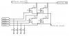
So, I have an external ADC, and external 5V source (pull up) and an external ground. I need to switch between different resistors on this signal without using my PIC's ground. That is, I need to force the signal through a resistor in order to change the voltage the ADC sees, but have to use an external ground.

Here is an idea I thought up. I'm not certain this is a job for a regular NPN or mosfet. The source pullup is 1K so this isn't a lot of current.

Is there a cleaner way to do this? I don't want to ground the resistors right to me because the external ground may be a lot cleaner.

Any thoughts?
 

Attachments

  • Capture.PNG
    Capture.PNG
    18.2 KB · Views: 245
Is the PIC not connected to the A/D? If it is then you must already have a common ground.

If you do really need complete ground isolation, then you could use opto couplers to transmit the signal between the PIC and the transistor switches.
 
The pic is NOT the ADC.

I have an original system that has a signal wire and a dedicated signal ground, this is where the pullup and the ADC are located. The signal wire has to go into my board where I need to direct it into a few different resistors.

Nigel, you sure that needs common ground? I was under the impression that as long as I power the gate on the mosfet, the current would freely go from A to B (but not B to A because of the mosfet's internal diode or acting there-of).
 
What's the bigger picture. Maybe there is an alternate solution.

I'm certain there is :)

I chose mosfets because of the uncommon ground (I mean, it's all connected to the same battery, my system and the original setup) but I'm not sure what actually makes up the dedicated ground circuit.
 
What is it for? What is anything for? :)

It's a replacement for some analog switches in a vehicle. Instead of a resistor ladder that is activated by pushing the buttons on the dash, I'm using a pic to take inputs from a touch screen and mimic the same resistor ladder using the outputs of the pic to (as per the plan) drive the gates of the mosfet, etc etc etc.

The important part is that I'd like to use their original signal return wire, although using common ground 'would' work.
 
If everything operates from one battery, then everything, by definition shares a common ground.
 
Their signal return isn't a real ground, it's dedicated for this tree. When the car is off it isn't ground, when the car is on it acts as ground but is at least some sort of diode somewhere. But, I do understand the idea of one battery, one common ground. This dedicated ground line they have I believe is to prevent noise from getting on that line. Or rather so that they can look at it differentially or something, I don't know.

Motorized volume control? Yea... that's a bit overkill for this!

I looked at digital pots for awhile, but iirc, they only handle upto 2ma and I think this circuit may be above that.

Are the mosfets a bad idea?
 
Tree? Car without GND? Strange stuff? How does the car disconnect itself from frame ground? How many mA do you need? Can you attach a photo of the analog switches on the dash?
 
No photo. It's just a complicated circuit board with small smd resistors all over the place.

The car has ground, but the signals often get their own ground wire or use a "sensor ground".

The ground circuit they have for signals (this one), is a "return" not truly a ground. Think of it as a dedicated VREF- just for this signal. I don't want to just throw that away since they found it important to have.

Tree / ladder... same to me.

So the idea I had was to use my micro to operate the gates on the fets to connect the signal wire to it's ground with the resistor of my choosing. Back to post 1 :)

I'm not acutally sure about the mA needed. I have one of these with a 1k pullup with the ladder ranging from 100ohm to 15k. The other is 2000 pullup with the same ladder. I'm not actually sure how to calculate what the pot would see for amperage. See, I'm not that smart, and never really learned this stuff ;) Do you take the pullup and the extra resistor and add them then use ohm's to take V/R and that is it? Or is it just the V/pullup since that's the max potential source current? I'm not sure.

Thing is, I only have a couple days to prototype it so I'm leaning on just using resistors and if I get a second opinion (here) I'll use the fets.
 
Status
Not open for further replies.

Latest threads

New Articles From Microcontroller Tips

Back
Top