Electro Tech is an online community (with over 170,000 members) who enjoy talking about and building electronic circuits, projects and gadgets. To participate you need to register. Registration is free. Click here to register now.
Welcome to our site! Electro Tech is an online community (with over 170,000 members) who enjoy talking about and building electronic circuits, projects and gadgets. To participate you need to register. Registration is free. Click here to register now.
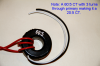
Using a CT you would find a suitable CT for the range you want. Attached is an example of a 60:5 CT using 3 turns in the primary making it effectively a 20:5 CT or a 4:1 ratio. With 11 amps flowing through the primary (red wire) the output would be 2,75 amps. Therefore using about a 2.75Ω resistor combination as a burden resistance would yield 1 volt RMS with 11 amps RMS flowing in the primary. That being just an example.
There are also other hall effect current sensors out there so it depends on what you want versus cost.
That line of sensors id discontinued and obsolete and to answer your question , no it would not work well as a hall effect current sensor. It does not afford an analog out but rather a schmidt trigger output.
I think what you are after is a "linear" hall effect sensor, or better yet and easier, a chip made with a hall effect sensor which can measure current.
A current transformer is normally used for AC current, except with special design. Hall effect sensors work better with DC though.
So you want to measure what? DC current? Should you want to measure DC current then you would use a hall effect sensor or a DC current shunt sensor. Additionally since you mention waveform then you would use a good hall effect sensor that is designed to measure true RMS current for waveforms other than a purely sine wave.
What exactly is the waveshape you want to measure and what is the frequency?
My circuit is a boost convertor which conver 12V 11A to 24V 4A with uc3843
My Problem is this: ( you can see the wave that we are thalking about) **broken link removed**
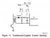
That circuit is intended for measuring the AC current through the transformer primary. It does so by rectifying the secondary voltage. The peak rectified (DC) voltage appears across the capacitor. You measure this DC voltage; it is proportional to the AC current. The waveform shown, across the resistor to the right of the diode, is irrelevant for this purpose.
Which resistor? Resistor from diode to capacitor or resistor parallel to capacitor. I'm not entirely sure the purpose of the resistor between the diode and the cap (maybe to limit charge current to the diode's current rating). The resistor to ground should most likely be a higher resistance, used to provide a discharge path for the capacitor in the event the incoming AC current drops, the indicated output voltage (across the capacitor) can follow.
This site uses cookies to help personalise content, tailor your experience and to keep you logged in if you register.
By continuing to use this site, you are consenting to our use of cookies.

") )
)