Continue to Site

Welcome to our site!

Electro Tech is an online community (with over 170,000 members) who enjoy talking about and building electronic circuits, projects and gadgets. To participate you need to register. Registration is free. Click here to register now.

  • Welcome to our site! Electro Tech is an online community (with over 170,000 members) who enjoy talking about and building electronic circuits, projects and gadgets. To participate you need to register. Registration is free. Click here to register now.

Need timer help.

Status
Not open for further replies.

godzzola

New Member
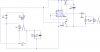
Hi. This is my first post here and I hope you guys can help me out. I am trying to build a timer circuit for the rear window defroster on my fathers car. I need to be able to turn on a 12v relay for 8 to 10 minutes but I need to be able to turn it on and off with a single, normally open, momentary pushbutton. In other words I need to be able to start the timer with a pushbutton and turn it off prematurely if need be with the same pushbutton. I thought I would be able to do this with a 555 timer but I can't seem to figure it out on my own. Any help would be great.
 
Hi godzzola,

welcome to the forum.

8 to 10 minutes is already an ultra long time delay and impossible to do using an NE555. I would work using a TLC7555 (CMOS version of the NE555).

The values for 600 seconds are: R=5.541MΩ and C=100µF, for 480 seconds use R=4.369MΩ.

Use a rocker switch at the timer output for manual override.

Boncuk
 
Last edited:
Thanks Boncuk. I'm trying to utilize the momentary switch that is already in the car. I need to be able to control everything with that switch to keep everything looking original. I would like to stay away from any other different switches.
 
Here is what I have so far. I would like to be able to use components instead of a relay to latch and unlatch the timer circuit. Any ideas?
 

Attachments

  • Rear Defroster Circuit.JPG
    Rear Defroster Circuit.JPG
    26.6 KB · Views: 273
Timer circuit

Hi godzzola,

your monostable wiring is wrong. Additionally the TLC7555 cannot supply a high power relay normally used in car electric. So you must use an extra transistor to drive the relay.

The schematic I made uses two switches (momentary). To activate the heater circuit apply a positive pulse to the input pin. Do deactivate it at any time press the reset button.

The timer circuit uses a 5M variable resistor. Fixed value resistors >1M are sometimes difficult to get.

The current limiting resistor for the LED is based on 13.8V car supply voltage. Don't forget to use good supply voltage filtering. CMOS devices are destroyed pretty fast being supplied with AC spikes on the DC.

There is also the possibility to omit one button using a CD4027 as a toggle switch circuit. (press once - on, press the second time - off)


Regards

Boncuk
 

Attachments

  • WINDOW-HEAT.gif
    WINDOW-HEAT.gif
    13 KB · Views: 264
This very clever circuit was posted a long time ago by KMoffett and it's a toggling relay circuit. This could be used to switch the 555 circuit on and off.
pushonpushoffrelay-gif.17791


For 12V the relay would need to be 6V.

Mike.
 
This very clever circuit was posted a long time ago by KMoffett and it's a toggling relay circuit. This could be used to switch the 555 circuit on and off.
pushonpushoffrelay-gif.17791


For 12V the relay would need to be 6V.

Mike.

Hi Mike,

on YES, off NO.
 
When the relay is energised and the switch is depressed the capacitor is connected across the coil and results in zero volts being available to hold the relay on as the discharged capacitor is effectively a short circuit.

Mike.
 
When the relay is energised and the switch is depressed the capacitor is connected across the coil and results in zero volts being available to hold the relay on as the discharged capacitor is effectively a short circuit.

Mike.

... still being unpredictable. Holding the switch for a longer period will result in self latching of the relay again.

This is what we call a "Hauruck" circuit in Germany. You might call it "raped electronics". :D

Hans
 
... still being unpredictable. Holding the switch for a longer period will result in self latching of the relay again.

Maybe, it depends on the relay. While the button is pressed the relay will only ever see 1/3 supply voltage due to the voltage divider formed by the resistors and the coil. Besides, auto repeat after a second or two would be quite logical.:D

As I said, "it's a very clever circuit" and I like it because it really makes you think in order to work out how it functions.:D

Mike.
 
Ok. I added a 4013 IC to toggle the momentary switch. The only problem is that if I wanted to turn on the timer circuit again I would have to press the momentary button twice to retrigger it. The relay at the end of the circuit is only used to trigger a larger automotive relay that originally powered the rear defroster. A transistor would probably be better.

Mike, I originally tried to use your "clever circuit" in my first design but it was too unpredictable. Thanks though. If anyone has any ideas on how to improve my latest circuit, please let me know. I'm just an amature and can use all the help I can get.
 

Attachments

  • Rear Defroster Circuit 2.JPG
    Rear Defroster Circuit 2.JPG
    34.7 KB · Views: 205
Hi godzzola,

you can avoid pushing the button twice using a CD4027. Properly wired its outputs Q and /Q change state with every button push. Using just output Q the output will go high with the first push, low with the second and high again with the third.

The relay option bears the risk of no switching effect if the button is held down too long.

I suggest to incorporate a low batt disable circuit. Assuming a cold start with the battery almost depleted it takes a while until good power is available. Activating the heater under low batt conditions will probably result in using jump cables in case the engine quits for some reason.

And once more again: You can't drive a relay directly from the TLC7555 output.

Boncuk
 
Last edited:
Hey. I have an engineering project where I need a timer for 24 hours. Could anyone give me the maximum time that a 556 dual is reliable for, or suggest another inexpensive option? thanks
 
Status
Not open for further replies.

Latest threads

New Articles From Microcontroller Tips

Back
Top