Continue to Site

Welcome to our site!

Electro Tech is an online community (with over 170,000 members) who enjoy talking about and building electronic circuits, projects and gadgets. To participate you need to register. Registration is free. Click here to register now.

  • Welcome to our site! Electro Tech is an online community (with over 170,000 members) who enjoy talking about and building electronic circuits, projects and gadgets. To participate you need to register. Registration is free. Click here to register now.

Need some help with keypads

Status
Not open for further replies.

unseen marine

New Member
Hey (I apologise if this is in the wrong place),

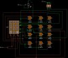
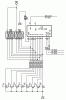
On my current circuit (its a electronic poker chip device) currently the inputs are PTM which send out pulses, however, I would instead like to give the option for the user to input the amount they want with a key pad - its the 3 x 4 one from RapidOnline. However, I have no idea on how to code the E28 chip to work with it - how would you go about coding it??

Best regards

Josh

P.S. I am using the latest circuit wizard.
 
Last edited:
Unfortunately i have the circuit you need but cannot open it as it has become corrupted.
What you have to do is as follows:

On the right hand side of the keypad [please excuse my insufficient knowledge of pin names], connect it to the outputs of the GENIE PIC.

Then, the bottom pins go to the inputs of the GENIE PIC.

What you want your flowchart to do is the following,

Say you want the number one, the right hand side pin of 1 is connected to Q0, which would be the first output.
The bottom pin of 1 is connect to D0, which would be the first input.

You flowchart would be like this...

START
l
Q0 HIGH
l
WAIT 0.25
l
D0 ON?
Y l
[CARRY ON]

does that help?
sorry im not too familiar with the theory behind it
 
I have attached a picture of the wiring of the keypad I wired up, however, each row, when pressed i.e. for the first row with the LED. When either 1, 2 or 3 is pressed it lights up the LED even though its only meant to be 1....
 

Attachments

  • keypad fail.JPG
    keypad fail.JPG
    44.5 KB · Views: 1,507
Well all your columns are at 9V, that won't work with a matrix keypad you have to scan the columns. What's with the logic gates?

Anyway the right way to do it requires 8 I/O pins and some pullups on the input lines. The lazy (and old fashioned way) is a MM74C922 if you can find one.
 
Well all your columns are at 9V, that won't work with a matrix keypad you have to scan the columns. What's with the logic gates?

Anyway the right way to do it requires 8 I/O pins and some pullups on the input lines. The lazy (and old fashioned way) is a MM74C922 if you can find one.

Hi

Thank you very much for the quick reply!.

What voltage should I have powering the columns then?

Regarding the MM74C922 I can't find it from the supplier my school goes to (not allowed to go any where else); do you know any other method I could use. And would this be possible:

The user enters upto 3 numbers of the keypad, they then press Enter (or the # key) this submits that number to a chip who converts that number into an amount of pulses.

Many thanks

Josh
 
Hi,

if you don't have to use a matrix coded keypad you might use individual keys connected to a parallel in - serial out shift register M74HC165.

Connect the serial output to the MCU (or to the next stage) and write the software accordingly.

Cascading chips you might connect an (almost) unlimited number of keys (buttons).

Boncuk

P.S. the jumper sets the first serial in pin to low.
 

Attachments

  • PAR-IN-SER-OUT.gif
    PAR-IN-SER-OUT.gif
    12.6 KB · Views: 780
Last edited:
Status
Not open for further replies.

Latest threads

New Articles From Microcontroller Tips

Back
Top