Electro Tech is an online community (with over 170,000 members) who enjoy talking about and building electronic circuits, projects and gadgets. To participate you need to register. Registration is free. Click here to register now.
Welcome to our site! Electro Tech is an online community (with over 170,000 members) who enjoy talking about and building electronic circuits, projects and gadgets. To participate you need to register. Registration is free. Click here to register now.
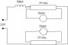
Was planning to make a double sided UV exposure box in the holidays, but I am a bit unsure om how to wire the different components.
I have made a wiring diagram but I am not sure it is correct, would be very happy for any feeback
Ok, But I se u have placed ballast on all UV lamps... but if I use a ballast on 30W I would be able to use it on two UV lamps shouldn't I?
With the hot side u mean where the positive voltage comes in?
Made a diagram to show what I meant that I could have 2 lamps per ballast, this is a wiring diagram I found in the datasheet for the product.
The ballast is on 30W while the UV tubes is at 15W each...
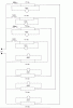
I am working on a diagram for 8 UV tubes but since I made to delete the last one I had to start from scracth :mrgreen:
edit: oops... that drawing is not correct the starter is not linked to both pins on the UV tube on the left upper field... it should only go to the lower pin...
Made a diagram to show what I meant that I could have 2 lamps per ballast, this is a wiring diagram I found in the datasheet for the product.
The ballast is on 30W while the UV tubes is at 15W each...
I am working on a diagram for 8 UV tubes but since I made to delete the last one I had to start from scracth :mrgreen:
edit: oops... that drawing is not correct the starter is not linked to both pins on the UV tube on the left upper field... it should only go to the lower pin...
I am a bit unsure how to connect those because in the datashet as far as I can se it doesn't stand where the power goes on the ballast...
And it seems like I should use capacitors when i use several togethers...
It is BTA 30L31 ballast wich I thought I use, it is a 30W ballast and I then use 15W UV tubes.
I did a little research and was reminded that, since fluorescent tubes are negative resistance devices, they cannot be paralleled off one ballast. However, they can be in series on 220V mains, but not on 110V mains. So... You should probably put pairs of them in series. Don't forget the switch.
One last question I think, if u se on the datashet the ballast got four connection pins (any more than two and I am confused ), anyway what I wondered is wich pins to use. I guess it is the two outer pins (on each side) but I am far from sure...
I will draw the "final" layout a little later today witch will includes switches and so on (I know of a pretty good diagram for a timer switch wich I know works, if I can get the I guess I use it...).
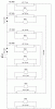
Now I am finished with the diagram I think I added 2 switches, one for main power and the other to switch between double sided exposure and singlesided.
Now I am finished with the diagram I think I added 2 switches, one for main power and the other to switch between double sided exposure and singlesided.
Now I am finished with the diagram I think I added 2 switches, one for main power and the other to switch between double sided exposure and singlesided.
I should manage not to get electrocuted since I dun wire as long as the power is conected (I am not that newb...), dun think sun burned is a problem either since I am going to build it inside a suit case (made of wood). I see if I post a picture of it when I am finished
Thought I come with some update if somebody else thinking of using this diagram or not (they propably want to know if I got electrofried or not ). I got a bit delayed because of some others thing I had to use the christmas on so therefore I started om working on it last saturday, and I am soon finished and it is working ond both sides
Thanks alot for the help!
This site uses cookies to help personalise content, tailor your experience and to keep you logged in if you register.
By continuing to use this site, you are consenting to our use of cookies.

")