Continue to Site

Welcome to our site!

Electro Tech is an online community (with over 170,000 members) who enjoy talking about and building electronic circuits, projects and gadgets. To participate you need to register. Registration is free. Click here to register now.

  • Welcome to our site! Electro Tech is an online community (with over 170,000 members) who enjoy talking about and building electronic circuits, projects and gadgets. To participate you need to register. Registration is free. Click here to register now.

Need Some Answers

Status
Not open for further replies.

Ednamosa

New Member
Hi Guys, I am getting some problems in followings

1> Can you Define an Electric Charge. Please don't describe it by an example.

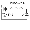
2> I have a battery of 24V and an unkown resistance is connected in series with a led. The circuit is series and simple. What is the formula to calculate resistance that should be keep to turn the led on.
 

Attachments

  • ckt.png
    ckt.png
    1.4 KB · Views: 969
1) An electric charge is simply just an electron or a proton.
For electrical systems it is the electron flowing that is the current moving


2) Without some infomation about the LED in question some assumptions need to be made

a) forward drop of LED = 1.2V
b) current for resonable brightness = 10mA

With these two rules-of-thumb so to speek the voltage dropped across the battery is equal to the difference between the Batery and the LED forward conduction drop


Vr = Vbat - Vled
Vr = 24 - 1.2
Vr = 22.8V

Now for a resistor V = IR
V is known and I is known so re-arranging

R = V/I

Thus R = 22.8/10e-3

R = 2280R
nearest value is 2.2KR


So overall Equ is:


(Vbat - Vled)/Iled
 
What is the Current of the LED?
What is the Foreward Voltage of the LED?

Typically you take the 24 volts and Subtract the LED Voltage.
Than divide this by the LED Curren to get the proper Resistance value.
 
Charge: (from my dictionary)
1. The electrical energy stored in a capacitor or on an insulated object.
2. The quantity of electrical energy in (1) above.

R = V/I
V is the voltage drop across the resistor = battery v - diode drop.
I is the desired current thru the diode.
 
As drawn, the battery is connected the wrong way round.

JimB
 
LED's are polarity sensitive and can be damaged with too high of reverse polarity. The anode needs to be positive and the cathode negative, or the reverse of that shown in the diagram. I haven't found a lot of information about the reverse breakdown voltage. I have one data book that list typical values of 4 to 5 minimum reverse breakdown voltage. That is why when operating LED's on AC two mothods to protect the LED are utilized.
1. put a regular diode in series with the LED
2. put a regular diode in parallel with the LED, with the cathode of the regular diode connected to the anode of the LED, and the anode of the regular diode connected to the cathode of the LED.
 
Kaon and Meson Theory

The led max operating voltages are 3V, if I issume the Voltages of led then the resistance will be different. Also that the battery and Led current is unknown. Then we have to find them too?.

I have found an article about Charge on https://en.wikipedia.org/wiki/Electrical_charge
 
Re: Kaon and Meson Theory

Ednamosa said:
The led max operating voltages are 3V, if I issume the Voltages of led then the resistance will be different. Also that the battery and Led current is unknown. Then we have to find them too?.

I have found an article about Charge on https://en.wikipedia.org/wiki/Electrical_charge
The max voltage is the max forward voltage , actualy u need the min forward voltage (which is equivalent to fw: voltage drop) to make the led light. if u don;t know the led current , take an average of about 10ma as said by styx
 
Current Problem

Hi, I have CE configuration Amplifier Please any one can find out Current on R1,R2,R3,R4,Ice,Ibc,Ibe and voltage drop on all resistance.
 

Attachments

  • ce.gif
    ce.gif
    1.5 KB · Views: 833
AKG

I have this feeling that you have just done someones school homework!

JimB
 
hey JimB i think your right i had a 555 astable circuit afew weeks ago where i had to do the same thing :) but i supose it is abit easier to get someone else to do it for you :lol:
 
akg said:
JimB said:
AKG

I have this feeling that you have just done someones school homework!

JimB
Maybe .. and who is the loser , definitely not me :D

:twisted: Next time you do someones homework AKG make sure you put in a few wrong answers so when the poster puts in his homework the teacher could ask how he came up with those figures and I'd love to be a fly on the wall hearing the explanation. :D
 
bryan1 said:
:twisted: Next time you do someones homework AKG make sure you put in a few wrong answers so when the poster puts in his homework the teacher could ask how he came up with those figures and I'd love to be a fly on the wall hearing the explanation. :D
point noted :D:D :twisted:
 
Not so Fast

Guys here is an attachment in which I shows the eq. ckt of the Ce amp circuit. The unknown resistnace network cant be solved with out finding the total current or the total resistance. How you find Total current or resistance. Can you tell me?. Used some sort of circuit solving software like Circuit maker or some others :twisted:

it is Impossssssssssssssible to solve such unknown branch ckt :oops: .
 

Attachments

  • ceeq.gif
    ceeq.gif
    3.9 KB · Views: 524
Re: Not so Fast

Ednamosa said:
Guys here is an attachment in which I shows the eq. ckt of the Ce amp circuit. The unknown resistnace network cant be solved with out finding the total current or the total resistance. How you find Total current or resistance. Can you tell me?. Used some sort of circuit solving software like Circuit maker or some others :twisted:

it is Impossssssssssssssible to solve such unknown branch ckt :oops: .

u need to have a look at H-parameter analysis of Transistors.
 
H-Parameters

Sorry for late reply and for using unapproriate behaviuor :oops: . After it can any one tell me the web address that where i can find learning article on H-parameters and please also tell me that what is Intrinsic stand-off ratio of UJT

Vp=n*Vbb+Vd ---------(1)

Where Vp is peak or firing Voltage

n(eta) is intrinsic stand-off ratio

Vbb is supply volts

Vd is diode junction voltage(0.3-0.7)


My question is Why we multiply eta to Vbb in equation1 and why it is used for finding Vp and also that how can we find Rb1 and Rb2 by using formula.
_
-->|
|_
 
Hey guys, just curious, what is the maximum ON current a jumbo white LED can take safely if I use a 555 IC on it at a frequency of 15 Hz and duty cycle of 10% ? I'm going to experiment with it as a strobe.
 
Status
Not open for further replies.

Latest threads

New Articles From Microcontroller Tips

Back
Top