Continue to Site

Welcome to our site!

Electro Tech is an online community (with over 170,000 members) who enjoy talking about and building electronic circuits, projects and gadgets. To participate you need to register. Registration is free. Click here to register now.

  • Welcome to our site! Electro Tech is an online community (with over 170,000 members) who enjoy talking about and building electronic circuits, projects and gadgets. To participate you need to register. Registration is free. Click here to register now.

need some advice for this circuit

Status
Not open for further replies.

infin

New Member
have an existing circuit that im trying to modify, any help much appreciated

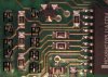
it has a motorola mc68hc705J1ACDW chip on it controlling a 7 segment (common anode) led display

what i want to do is when the segment displays a "7" i want it to trigger something else.

where im running into a problem is the voltage on each segment pin reads 5v+ when its displaying a 7, i thought since its common anode the mc68 should output (-)

how can i get this to work since all the lines are +5 or is a logic low and high different than +5 and gnd?

im going to be using a programabe chip sx28 programed for simple logic.
 
Nigel Goodwin said:
How many digits is the display?, if it's more than one it's almost certainly multiplexed.

its just a single 7 segment display, pin1,6 anode pin2,3,4,5,7,8,9,10 are for the segments. I guess my main question is if i wire in like a simple AND gate since all the voltages are reading +5 will they all be considered "hi", how will i get the "lo" reading from the other chip.
 
How about posting the schematic?
 
i dont have the schematic for the original circuit im working with, im trying to adapt to it, but its a very simple one, posted is what the main part of the circuit is.

I labeled the pinouts of the 7 segment display, how the circuit is setup:

The MC68HC is outputing a lo signal throught a 470 resistor straight to the led segment to illuminate it. Since its common anode there is constant 5+ at p1 and p6.

When i measure the voltage at all the pins on the segment im reading +5 even though all the segments are not lit.

How do i setup an additional circuit to read the "lo" coming from the MC68HC is what im trying to figure out, or will a normal logic gate be able to determine what ones are lo and hi?

Thanks!
 

Attachments

  • circuit.JPG
    circuit.JPG
    114.3 KB · Views: 155
Last edited:
infin said:
The MC68HC is outputing a lo signal throught a 470k resistor straight to the led segment to illuminate it. Since its common anode there is constant 5+ at p1 and p6.
Those are 470 ohm resistors.

infin said:
When i measure the voltage at all the pins on the segment im reading +5 even though all the segments are not lit.
This is what I would expect. When the segments are OFF, the voltage on the cathodes must be 5 V. When they're ON, the voltage at the mcu output pin must be about 0.

EDIT: corrected.
 
Last edited:
eng1 said:
This is what I would expect. When the segments are OFF, the voltage on the cathodes must be 5 V. When they're ON, that voltage must be about 0.

this is where im having a problem, if the segments are on or off, they always read 5v, there is no change. i did connect a gnd(lo) to one of the segments that wasnt lit and it does illuminate.
 
Russlk said:
How are you reading the voltage? An oscilloscope might give you a clue.

DMM, i would think it would read just fine with the DMM since its just hi and lo signals right? or am i missing something.
 
infin said:
this is where im having a problem, if the segments are on or off, they always read 5v, there is no change. i did connect a gnd(lo) to one of the segments that wasnt lit and it does illuminate.

I am surprised that it did not burn. Those resistors are there for reason. When segment is on, there should be 5V on anode and about 3.5V on cathode, rest of the voltage is dropped in resistors.
You should get 0V on the MCU side of resistor and that is where you should connect inputs of your gates.
Jirka
 
augh this circuit is killing me, no voltage drop, even at the mcu its 5v, im not how this thing is even operating.
 
You should read 0 V at the output pin of the mcu and about 2.5 V after the resistor (cathode of the LED) when the LED is ON.
Even if there is one display on the board, I start thinking that it's supplied with pulsed current. The multimeter can't read the voltage properly in that case.
 
Last edited:
after stduying the circuit more, this thing is multiplexed! looks like im gona have a fun time sorting this out now. thanks all for you help much appreciated.
 
hi infin

I have made a drawing of the 7 segment LED, perhaps it will help you visualise why you think you are getting 'strange' readings.

Showing a single 7 seg and two multiplexed 7 seg LED's

Have a look, ask if you don't understand.

EricG

Edit:
Note on the 2 digit mux ONLY one set of 7 resistors are required, NOT one set per digit. Woops.
 
Last edited:
You have a set of resistors for each digit in mxed drawing. There should be only one set with leads splitting from resistors to cathodes of individual digits.
Jirka
 
infin said:
after stduying the circuit more, this thing is multiplexed! looks like im gona have a fun time sorting this out now. thanks all for you help much appreciated.

There is no reason for single digit to be multiplexed. Where do you connect negative lead of your DMM when you take measurements? Did you try measure directly across resistors? It should show some voltage even if it is pulsed. If you have available analog voltmeter, try that, they are better at averaging pulsed signals.

By the way AND gate will not be enough to decode "7", because same segments light up in 0,3,7,8,9. You will also need NOR gate for unlighted segments.
Good luck, Jirka
 
hi jirka
You have a set of resistors for each digit in mxed drawing

You are correct!.
Just my lazy way of copying the single digit to show a mux two digit.

Many thanks

Regards
EricG
 
Jirka46 said:
I am surprised that it did not burn. Those resistors are there for reason. When segment is on, there should be 5V on anode and about 3.5V on cathode, rest of the voltage is dropped in resistors.
You should get 0V on the MCU side of resistor and that is where you should connect inputs of your gates.
Jirka

Actually most CMOS self limits and micro pins tend to have lower current drive than logic chips.

More often than not, while it may not be recommended, on low drive outputs you can rely entirely on the pin limitations to keep the LED drive current in check...but this should never be done in actual practice.

This could be handy if the processor states that the pin drive capacity is lower than the pin absolute max. In this case you could actually use the drive capability as the LED current limit as long as you do not exceed other chip limitations.

D.
 
Status
Not open for further replies.

New Articles From Microcontroller Tips

Back
Top