Continue to Site

Welcome to our site!

Electro Tech is an online community (with over 170,000 members) who enjoy talking about and building electronic circuits, projects and gadgets. To participate you need to register. Registration is free. Click here to register now.

  • Welcome to our site! Electro Tech is an online community (with over 170,000 members) who enjoy talking about and building electronic circuits, projects and gadgets. To participate you need to register. Registration is free. Click here to register now.

Need Schematic Checked

Status
Not open for further replies.

madcitysw

New Member
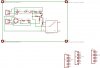
Hello, I been designing a power board that uses a 12V relay to switch on the switched side terminals on when it gets a 5V+ from a AVR. I would like someone here to look over my schematic and see if I need to change something. I also need help getting values for the R3 & R4 as I don't know how to calculation that part yet. The relay will output 12V+ at 30 amps.

F1 = 30 Amp Fuse
X1 = 12V @ 30 Amp (Pin 1 = +, Pin 2 = Ground)
X2 = 5V @ 1 Amp Logic (Pin 1 = +, Pin 2 = Ground)

All part number is on schematic if you need that to help out. Also check to see if I connected the PNP correct and all, and one more thing, should I hook up the ground from the 12V terminal to the 5V terminal ground as one?

Thanks
Shane
 

Attachments

  • relay_board.JPG
    relay_board.JPG
    155.8 KB · Views: 173
Last edited:
I would have feed the LED in the opto from the AVR side. An opto triac could also be used as there is no filtering from the bridge rectifier. Feeding the opto LED from the AVR side will simplify the circuit. Sorry, I just had a closer look and you arenot using an opt, simply an LED and transistor drawn to look like an opto.
 
Last edited:
Super_voip said:
I would have feed the LED in the opto from the AVR side. An opto triac could also be used as there is no filtering from the bridge rectifier. Feeding the opto LED from the AVR side will simplify the circuit. Sorry, I just had a closer look and you arenot using an opt, simply an LED and transistor drawn to look like an opto.

Ya, it is kind of hard to really see where the parts are connected to with that tiny picture :(

Thanks for helping though.
 
madcitysw said:
I would like someone here to look over my schematic and see if I need to change something. I also need help getting values for the R3 & R4 as I don't know how to calculation that part yet.
What is the relay coil current?

The transistor base current needs to be about 1/10 th of the relay current.

However, it is not going to work as drawn.

You need a connection between the cathode of LED2 and the left hand side of R4. But this may cause a problem due to the 2 AC sources.

So you may need an opto to drive the transistor.
 
Last edited:
ljcox said:
What is the relay coil current?

The transistor base current needs to be about 1/10 th of the relay current.

However, it is not going to work as drawn.

You need a connection between the cathode of LED2 and the left hand side of R4. But this may cause a problem due to the 2 AC sources.

So you may need an opto to drive the transistor.

OK i getting a little lost. Those two leds just there just to tell me if it was getting power from the terminals. I was thinking about connecting both ground from the 12V terminal & 5V terminal together as one. There is a connection on both ends of led2. Look closely. Is there anyone else want to say anything?
 
is the voltage from both supplies DC, if either or both are AC as it looks likely from the circuit(bridge diodes) the earth (0V) rails won't really be 0V, there will be some voltage difference between them. This is why optos get used.
 
Status
Not open for further replies.

Latest threads

New Articles From Microcontroller Tips

Back
Top