Nigel Goodwin said:
Using two 555's like that is a complete receipe for disaster! - it's bound to turn all four transistors on at the same time, blowing all four transistors, and possibly causing other damage as well (depending on the supply).
I can't believe anyone would tell you to do it that way!, perhaps you misunderstood?.
Yes using two 555 is a very bad idea, but as I stated, this topology is the safest one for it to accedently done two.
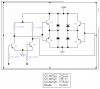
The phase-legs are in a PUSH-PULL configuration, thus only one transistor per leg will be on => no problem.
IF one input LOW and other HIGH => normal operation
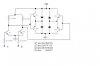
IF both inputs LOW => both upper PNP will be ON, this provides a zero-voltage loop around the top
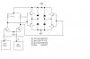
IF both inputs are HIGH => both lower NPN will be NO, this provides a zero-voltage loop around the bottom
uncle_sam:
What I mean is take a 555 as the source of your PWM.
Now the H-bridge takes two inputs (as you can see), these inputs should be the complement (ie inverse) or each other. IF they are not you end up with the zero-loop configuration I just mentioned. This isnt bad and in some cases extreamly beneficial.
Anyway so you need an inverted PWM signal? Use an inverter/NOT gate.
so you have one PWM from the 555, feed it into the NOT gate and you end up with !PWM.
feed the !PWM into one input and PWM into the other input and it will work fine