Continue to Site

Welcome to our site!

Electro Tech is an online community (with over 170,000 members) who enjoy talking about and building electronic circuits, projects and gadgets. To participate you need to register. Registration is free. Click here to register now.

  • Welcome to our site! Electro Tech is an online community (with over 170,000 members) who enjoy talking about and building electronic circuits, projects and gadgets. To participate you need to register. Registration is free. Click here to register now.

need hitech config help

Status
Not open for further replies.

anoopmb25

New Member
hi sir,
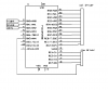
am using pic18f2550 for a 10 x 5 matrix project but i dont know how to configure it as

internal oscillator 8mhz ra6 as i/o port
1:16 prescaler
16 bit mode pls help me my code is below is it correct i dont nedd usb and other such things
using below code interrupt not working

Code:
__CONFIG(1, IESODIS & FCMDIS & INTIO);
// Config word 2
__CONFIG(2, VREGEN & PWRTEN & BORDIS & WDTDIS);
// Config word 3
__CONFIG(3, PBDIGITAL & LPT1DIS & MCLREN);
// Config word 4
__CONFIG(4, XINSTDIS & STVRDIS & LVPDIS & ICPORTDIS & DEBUGEN);
// Config word 5, 6 and 7 (protection configuration)
__CONFIG(5, UNPROTECT);
__CONFIG(6, UNPROTECT);
__CONFIG(7, UNPROTECT);

main

Code:
void main(void)
{
OSCCON=0x70;
T0CON=0x83;
TMR0H=0xFF;
TMR0L=0xF6;
INTCON=0;
INTCON2=0;
INTCON3=0;
PIR1=0;
PIR2=0;
PIE1=0;
PIE2=0;
IPR1=0;
IPR2=0;
IPEN=0;
ADCON0=0;
ADCON1=0x0f;
ADCON2=0;


T1CON=0;
T2CON=0;
T3CON=0;

SSPCON1=0;
SSPCON2=0;
RCSTA=0;
TRISA=0b00000111;
TRISC=0b10000000;
TRISB=0;
PORTA = 0b00000000;
PORTB = 0b00000000;
PORTC = 0b00000000;
CCP1CON=0,
CCP2CON=0;

SPBRG=51;
TXSTA=0x22;
RCSTA=0x90;
BAUDCON=0x48;
SPBRGH=0;
POR=1;
//displayClear();

IPEN=1;

GIEH = 1;
GIEL = 1;
//INTCONbits.PEIE = 1;
TMR0IE = 1;
//displayPlot(2,3,ON);
	while(1)
	{
//displayPlot(2,3,ON);
COL_0=1;
COL_1=1;
COL_3=1;
 ROW_0=1;
ROW_1=1;
 ROW_2=1;
ROW_3=1;
 ROW_4=1;
	}
}

interupt

Code:
void interrupt low_priority lpHandler(void)
{
	unsigned char rowCounter;

	// Is this timer0 interrupting?
	if (TMR0IF)
	{
COL_0=1;
COL_1=1;
COL_3=1;
 ROW_0=1;
ROW_1=1;
 ROW_2=1;
ROW_3=1;
 ROW_4=1;
		TMR0L = 0xF6;	// Reset the timer0 counter
		TMR0IF = 0;	// Clear the timer0 interrupt flag
	}
}


please help me
 
You forgot to set the correct System Clock Select Bits <OSCCON 1:0> to select the internal oscillator block as the system clock. Try changing "OSCCON=0x70" to "OSCCON=0x72".
 
Last edited:
OSCCON=0x70 in this mode its working fine in mplab c18 compiler


when using OSCCON=0x72 interrupt not working but main function started working

thanx
 
Last edited:
OSCCON=0x70 in this mode its working fine in mplab c18 compiler

When you say "it's working fine" are you saying that the internal oscillator is working as an 8MHz oscillator? Also, did you even try "OSCCON=0x72"?
 
when using OSCCON=0x72 interrupt not working but main function started working

means when i set all rows and columns ON in main function(in while(1) its working

but when i set all rows and columns ON in interupt routine its not working


thanx
 
Last edited:
ya its working as 8mhz oscillator in mplab c18 compiler i changed to hitech compiler becoz asccii table storage problem in mplab c18 compiler


wat wil be the problem pls help me
 
Last edited:
This is one off these time when both work there only 3 bits that set for 8 mhz IRCF2:IRCF0: which can be 0x70 or 0x72
or any combination that set IRCF2:IRCF0 to 111 But that don't mean they will turn on the oscillator 0x70 and 0x72 will turn on
at full speed but if you set this wrong 1: Depends on the state of the IESO Configuration bit. 0x70 will not work

So to use 0x70 this has to set IESO Configuration bit 0 = Oscillator Switchover mode disabled in your config

The old saying there more then one way to skin a cat there is LOL

This is one off them LOL
 
Last edited:
I don't like Hi-tech to much It changes to much with each update

Here a little Hi-tech sample to look over
Code:
void init(void)
{
	T1CON=0x80;	/* we are testing  TIMER1 */
	T1CKPS1=RA1;/*update values of prescalar bits*/
	T1CKPS0=RA0;  

	TMR1IF=0;/* Clear overflow flag*/
	TMR1IE=1;/* Enable TIMER1 interrupts */	
	TMR1=0;/*Load initial value to TIMER1*/

																						
	T3CON=0x00;/*use TIMER3 as reference for comparison*/
	TMR3IF=0;																	
	TMR3IE=1;																
	TMR3=0;	/*Load initial value to TIMER3*/

	RBIE=1;	/* enable PORTB interrupts to */
	GIEH=1;	/* allow interrupts from PUSH BUTTONS */
	GIEL=1;	

	TXEN=1;/* enable serial port transmissions */
	SPEN=1;				
	TXIE=0;	/* not interrupt driven */		

	TRISA=0x03;	/* Set first 2 bits to input to read DIP switch values */
																						
	ADCON1=0x0F;/*configure pins of PORTA to be digital inputs*/

	TRISB=0xF0;/* Push button is connected to   RB4 to turn timers ON and OFF*/
	TRISC=0x01;/* 1bit LED panel is connected to RC1 to indicate TIMER1 ON/OFF status*/
			/* Push button connected to  RC0 is used to test TIMER1 as a counter*/
	TRISH=0x00;/* LED panel indicates frequency of TIMER3*/
	TRISE=0x00;/* LED panel indicates current frequency of TIMER1 */
	TRISF=0x00;/* LED panel shows current value of register TMR1L */
	TRISD=0xFF;/* 8-bit DIP switch to set  value of LED pannels */
	
	LED1=PORTD;	/*Load LEDs with current value of 8-bit DIP*/
	LED2=PORTD;
	LED3=TMR1L;	/*Load LED3 with  current value of TMR1L*/
	UPDATE_REQUIRED=1;
}

This is for timer0
[
Code:
void init(void)
{
	T0CON=0x4E;
	TMR0IF=0;			/* Clear overflow flag*/
	TMR0IE=1;			/* Enable TIMER0 interrupts */	
	
	T0PS2=RA2;
	T0PS1=RA1;			/*update values of prescalar bits*/
	T0PS0=RA0;  
	
	T1CON=0x80;			/*use TIMER1 as a reference for comparison*/
	TMR1IF=0;																	
	TMR1IE=1;																

	RBIE=1;				/* enable PORTB interrupts to */
	GIEH=1;				/* allow interrupts from PUSH BUTTONS */
	GIEL=1;	
	
	TXEN=1;				/* enable serial port transmissions */
	SPEN=1;				
	TXIE=0;				/* not interrupt driven */		

	TRISA=0x17;			/* Set first 3 bits to input to read DIP switch values and*/
					/*4th bit for counter, clock input */
	ADCON1=0x0F;			/*Configure all ADC pins  to be digital inputs*/

	TRISB=0xF0;			/* Pushbutton switches to change TIMER0 status are on PORTB */
	TRISC=0xBF;			/* LED panel to indicate oveflows of TIMER0*/
	TRISH=0x00;			/* LED panel to indicate oveflows  of TIMER1*/
	TRISD=0x00;			/* 8-bit DIP switch to set  value of LED pannels */
	TRISF=0x00;			/* LED panel to indicate current  value of TIMER0*/

	TRISE=0xC0;			/* LED panels to indicate current mode of the TIMER0*/

	TMR0=1;				/*Load initial value to TIMER0*/

	LED1=DIP1;			/*Load LEDs with current value of 8-bit DIP*/
	LED2=DIP1;
	LED3=TMR0L;			/*Load LED3 with current value of TMR0L*/

	UPDATE_REQUIRED=1;
}
 
Last edited:
If you would Like tell what your trying to do would help?
You can scan your led's without using the timer0 Nigel has a 64 led board
Your just wanting 50 which would work with a little changes to hardware and coded in C

You can use the timer0 to fire your led's on time and scan your led's. But it's hard to see what your trying to do here
no schematic
I would lay out a plan

This uses simple loop for timing

This one to show a pic can light some leds the boards Nigels idea no divers just fast scaning and the Pic never reached 80ma
 
Last edited by a moderator:
i am trying to make break light system for my bike

i made a 10 x 5 led matrix display using pic18f2550 and 10 bc548 transistor for 10 columns (negative supply) and 5 bc548 and 5 bc557 coupling for 5 rows(positive supply). positive supply is from a lm317 ic its the basic hardware

pic is configured as 16 bit internal oscillator using 1:16 prescaler for better row scanning


actually i made this project for my bike and it is interupt driven and wish to control the brightness via pwm

Say for example,
total 3 interrupts
one for breaklight and other two for turning indicator
when the circuit is powered it is in park light mode that is all leds on with less brightness
on default no power supply given to circuit and working is given as follows

when park switch is on only power supply goes to circuit without any interrupts and it is in low brightness mode

on break signal power supply and respective interrupt is gone to circuit and same for turning signal

but the timer0 interupt not working
pls help me to blink an led using these config then i can do rest
 
Last edited:
I see now a little better You don't need interrupt to scan stop, right, left, park. I would use it for led on time park 50% bright
stop, left, right, full bright I try to post you something after collage classes I'm finishing it after 30 years LOL but then I can could say I'm a EE lol.
 
There a errata for the 18f2550 and Hi-tech I tried the same code just changed to swordfish and timer0 works fine use the same setting in Hi-tech and it will not come on.
 
You put these in one folder first one you can name what ever you want like main.bas the last one has be saved as timer0.bas

This is just a sample showing how to set up timer0 and count out on PORTB with some leds

Code:
Device = 18F2550
Clock = 8
Config FOSC= INTOSCIO_EC


Include "timer0.bas"
Include "utils.bas"

Dim LEDS As PORTB

Event LEDFlash()
      LEDS=LEDS +1 
End Event

Interrupt ISR()
     INTCON.7=0
     If Timer0.InterruptFlag =1 Then
        Timer0.SInterrupt()      
     EndIf
     INTCON.7=1
End Interrupt

// main
Utils.SetAllDigital()
OSCCON = $72
ADCON1 = %00001111
TRISB = %00000000
PORTB = %00000000


Timer0.Initialize(LEDFlash)
Timer0.SetPrescaler(Timer0.PS2)
Timer0.EightBit = 0
Timer0.Preload=1000
Timer0.EnableInterrupt()
Timer0.Enabled()
Enable(ISR)

While true
Wend

timer0.bas
Code:
Module Timer0

Type TEvent = Event()

Public Const 
      SRCInternal = 0,
      SRCPIn = 1,
      EDGEFalling = 1,
      EDGERising = 0,
      PSDisabled = 1,
      PSEnabled = 0,
      PS256=7,
      PS128=6,
      PS64=5,
      PS32=4,
      PS16=3,
      PS8=2,
      PS4=1,
      PS2=0

Dim FPreload As Word,
    FPrescaler As Byte,
    FEnabled As T0CON.7,
    FInterrupt As INTCON.5,
    OnISR As TEvent

Public Dim 
       Preload As FPreload,

       EightBit As T0CON.6,
       Source As T0CON.5,
       Edge As T0CON.4,
       PrescalerEnabled As T0CON.3,

       InterruptFlag As INTCON.2

Public Sub Enabled()
       TMR0L = FPreload
       FEnabled=1
End Sub

Public Sub Disabled()
       FEnabled=0
End Sub

Public Sub EnableInterrupt()
       FInterrupt=1
End Sub

Public Sub DisableInterrupt()
       FInterrupt=0
End Sub

Public Sub ClearInterrupt()
       InterruptFlag=0
End Sub

Public Sub SInterrupt()
       OnISR()
       TMR0L = FPreload.Byte0
       TMR0H = FPreload.Byte1
       ClearInterrupt()
End Sub

Public Sub SetPrescaler(ByVal pPrescaler As Byte)
       Select pPrescaler
              Case PS2
                   FPrescaler = PS2
                   PrescalerEnabled=PSEnabled
              Case PS4
                   FPrescaler = PS4
                   PrescalerEnabled=PSEnabled
              Case PS8
                   FPrescaler = PS8
                   PrescalerEnabled=PSEnabled
              Case PS16
                   FPrescaler = PS16
                   PrescalerEnabled=PSEnabled
              Case PS32
                   FPrescaler = PS32
                   PrescalerEnabled=PSEnabled
              Case PS64
                   FPrescaler = PS64
                   PrescalerEnabled=PSEnabled
              Case PS128
                   FPrescaler = PS128
                   PrescalerEnabled=PSEnabled
              Case PS256
                   FPrescaler = PS256
                   PrescalerEnabled=PSEnabled
              Else
                   PrescalerEnabled=PSDisabled
       End Select
       T0CON.0=FPrescaler.0
       T0CON.1=FPrescaler.1
       T0CON.2=FPrescaler.2
End Sub


Public Sub Initialize(pEvent As TEvent = 0)
       Disabled()
       EightBit = 1
       Source = SRCInternal
       PrescalerEnabled = PSDisabled
       DisableInterrupt()
       OnISR = pEvent       
End Sub
 
Last edited:
Here a little sch to start with I need to see your led hookup. anode + and cathnode-
 

Attachments

  • bike.PNG
    bike.PNG
    4.4 KB · Views: 142
Status
Not open for further replies.

Latest threads

New Articles From Microcontroller Tips

Back
Top