Continue to Site

Welcome to our site!

Electro Tech is an online community (with over 170,000 members) who enjoy talking about and building electronic circuits, projects and gadgets. To participate you need to register. Registration is free. Click here to register now.

  • Welcome to our site! Electro Tech is an online community (with over 170,000 members) who enjoy talking about and building electronic circuits, projects and gadgets. To participate you need to register. Registration is free. Click here to register now.

need help with triac

Status
Not open for further replies.

aruna1

Member
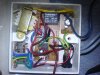
hi, i'm working on a timer circuit to control a water pump.I used a BT139 as pump control switch.my problem is triac heats to very high tempreture.i guess its because i use it with its ful capacity.i dont have enough space to connect a heat sink as the circuit is tightly fitted into the box.i was wandering if i connect 2 or more BT139 triacs parallely can i reduce the heat?(is it possible to connect triacs parallely and oparate them with single MOC3023?) I checked for 40amp triac(BTA40) and its really really expensive.
 
Hi what do you mean by 'each leg'? its a 220v pump,connected to single phase line?
do u mean 1 triac for live and one for nutral?
circuit i use is one from moc3020 datasheet.i cant upload cct as i have logged in using my phone.
and relay is not an option due to the space limitation.what about parallel connection of two triacs?
 
I see you have very little space but in order to control this pump you may need more space.
Using a solid state device for on/off of high amperage devices creates heat thus you have discovered this.
Is it possible to insert a relay at the other end of the electrical supply?
this may be a better option?
 
Oh yea putting two in parallel won't work. Each one would still carry the 40 amps.
 
well actually pump is connected to 15 amp line.so i assumed it draws all 15amp and thats why i decided to use BT139 as its 16amp triac.i was looking for 40amp triac so its well beyond safe current.anyway how come if i connect two triacs parrelle it still go max current through each device? its like two switches in parellel.shouldn't current divide in to two?we connect 7805 regulators parallaly to increase current capability.right? i have constructed the circuit inside a 15 amp socket outlet(its where stop is plugged in to) so i really like non-relay solution. thanks
 
I don't see why you'd need more than one TRIAC unless it's three phase or split phase.

The TRIAC will heat up, there's no way of avoiding that.

I don't see how using two TRIACs in parallel could possibly help unless you use two opto-couplers and even then they wouldn't current share very well. With one opto-coupler, the fastest TRIAC will just fire, leaving the other one redundant.

Using zero crossing (MOC3041) and a snubber network will give the TRIAC and easier life but it will still need to use the same amount of heat.

Is it possible to use the fluid being pumped as a cooling medium?

If it's a copper or brass pipe you could mount it to a metal plate joined to the pipe (with a suitable insulator and earthing of the pipe) which should act as a very good heat sink.

How much current does the pump need?

What about just using a relay?
 
hi,its 15amp what my cct does is turn on pump for 10 min and turn off it.so wont both triacs fire?may nt be simualtaniously but with a delay of few seconds
 
No, when the first TRIAC fires the votlage across the opto-coupler will be very low so the other is unlikely to fire.
 
oh i see,then i hv to move for two optocouplers or for a relay.
relays with current rating more than 10A is hard to find here.bringing one from abroad is time consuming and expensive.so is it possible to parallel 2 relays?
and if i use 40amp triac to control this 15amp pump,will it still discipate high heat?
and can u suggest cheap triac with high current rating for this? BTA40 cost a fortune.
 
Are you sure the motor actually draws 15A, have you measured it?

Just because it's on a 15A breaker, it doesn't mean it actually draws 15A.
 
hmm i just assumed the value.i cant measure it as my multimeter cant measure more than 10amp. what would be the safe current i should use? 20amp? 30amp? can i use power rating of motor to get the current (p=vi)
 
You shouldn't make assumptions like that, the breaker rating is often as much as twice the appliance's current rating, especially with devices containing large motors such as pumps.

You need a clamp meter to measure the actual current consumption.
 
read the plate on the motor for the specs.
a 15 amp pump, it could be 110v??
we need more info
and as far as two 7805's in parrallel, its a no no.
this has been discussed before. to do it right (the 7805 with more current) you add a high power transistor, not another 7805.
do a search for 7805 more current.
now back to your pump. get the motor specs and look into switching the power off/on at other end of power input. like right next to the breaker pannel.
 
The "other end" is perhaps the breaker box that has all the circuit breakers in it.
I assume your pump is located out in the field or away from the house located in an out building.
The power company has a meter near the breaker box. This is the other end.
 
FINALLY ts done

Hi all,
Just found out that the water pump was 4.1A rating pump [0.75hp,4.1A,0.56W,220v] connected to 15A line.(took lot of time to find the pump box.) so i was able to use a small relay,(small enough to fit there,but had to cross 125km to find it :p
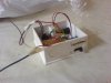
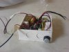
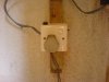
).as first I couldn't find the pump details,initially i assumed it draws all 15A when operating and try to find a relay that can handle 15A.but now as it becomes 4.1A,I used a small 7A relay.It worked then had a problem of self triggering timer when relay turns off, and After adding some capacitors and diodes that problem was solved, and i have fixed it in a box and fixed it to the wall.

It works nicely now:) (I guess);) we will see how it perform in future)

So I want to thank everyone who helped me with this

THANK YOU
 

Attachments

  • DSC02178..jpg
    DSC02178..jpg
    113 KB · Views: 302
  • DSC02169..jpg
    DSC02169..jpg
    61.9 KB · Views: 235
  • DSC02168..jpg
    DSC02168..jpg
    64.4 KB · Views: 240
  • DSC02181..jpg
    DSC02181..jpg
    71 KB · Views: 210
Post a schematic to be sure you have the relay connected right.
Just because it works does not guarantee it will continue to work.
A diode across the relay coil
A capacitor across the relay contacts to reduce arcing.
Etc etc
Glad you got it working
 
How much space is there between the mains and DC tracks on the board?

There should be clearance of at least 7mm.

Have you connected a snubber network across the relay contacts? If not connect 100nF and 100R in series across the contacts.

A resistor with the same value as the relay's coil connected in series with the back EMF suppression diode will also help to prolong the contacts life.
 
Status
Not open for further replies.

Latest threads

New Articles From Microcontroller Tips

Back
Top