Hi everyone,
I have built a temperature controller. However, I wish to add some time delay for the relay to trigger off.As when the temperature drop to the boarder line, the relay will turn on and off in high speed.
So,what should I do to make 10 secs of time delay,so the temperature will be more "stable"
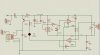
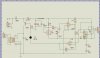
Attachment is my circuit design
I have built a temperature controller. However, I wish to add some time delay for the relay to trigger off.As when the temperature drop to the boarder line, the relay will turn on and off in high speed.
So,what should I do to make 10 secs of time delay,so the temperature will be more "stable"
Attachment is my circuit design


")
