Electro Tech is an online community (with over 170,000 members) who enjoy talking about and building electronic circuits, projects and gadgets. To participate you need to register. Registration is free. Click here to register now.
Welcome to our site! Electro Tech is an online community (with over 170,000 members) who enjoy talking about and building electronic circuits, projects and gadgets. To participate you need to register. Registration is free. Click here to register now.
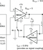
The DC position couples both the AC and DC portion of the signal, it's DC coupled. In the AC position only the AC portion is coupled. It connects a feedback integrator which acts the same as if there were a high-pass filter coupling capacitor in series with the output (there's a notation on the schematic which tells you that the HPF -3dB point is 0.5Hz). The advantage of the integrator is that you can use a high resistor to generate a low-frequency rolloff, which may not be practical with the usual LPF in series with the output.
This site uses cookies to help personalise content, tailor your experience and to keep you logged in if you register.
By continuing to use this site, you are consenting to our use of cookies.