Hi, I'm trying to build this kit myself instead of buying it because it's expensive.
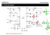
DC TO PULSE WIDTH MODULATOR
Velleman Components n.v.
datasheet https://www.electro-tech-online.com/custompdfs/2009/02/illustrated_assembly_manual_k8004_rev3.pdf
My problem is that I can't find the required mosfet BUK9535-55
datasheet here: http://www.datasheetcatalog.org/datasheet/philips/BUK9535-55.pdf
I can order my parts from:
Farnell LT | pasaulyje lyderiaujantis elektronikos ir technin?s prie?i?ros, remonto ir valdymo produkt? platintojas.
http://www1.elfa.se/elfa~eu_en/b2b/start.do
Could you help my find compatible mosfet or alternative circuit that would help me to control DC motor up to 12V.
I don't know how many Amps I need since the motor is from a printer and I can't find exact specs.
I have Canon Printer Carriage Motor QK1-1500
TN425813
A circuit that would keep constant speed is preferred.
Thanks.