Continue to Site

Welcome to our site!

Electro Tech is an online community (with over 170,000 members) who enjoy talking about and building electronic circuits, projects and gadgets. To participate you need to register. Registration is free. Click here to register now.

  • Welcome to our site! Electro Tech is an online community (with over 170,000 members) who enjoy talking about and building electronic circuits, projects and gadgets. To participate you need to register. Registration is free. Click here to register now.

Need Help With Power MOSFET Circuit

Status
Not open for further replies.

Bigmax

New Member
I'm trying to design a circuit using a Power MOSFET to drive a resistive load.

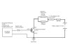
The way the circuit is hooked up now is the two grips are in series and connected directly to the ECU. I want to run the grips in parallel to increase the current, and power, to them. So basically I want to use the PWM signal from the ECU to drive a MOSFET so that the increased current goes through a $3 MOSFET instead of a $683 ECU. The attached diagram should help this all make sense.

Some questions I have:

1) Will this work?

2) Do I need the resistor to limit the current to the Gate? The ECU is capable of providing ~10A @ 12-14VDC.

3) What would the power to the grips and the series resistor be if the series resistor were 1.0 Ohm?

Any thoughts or suggestions (or totally re-design) would be greatly appreciated.

Thank,

Chad Wilson
 

Attachments

  • HandWamerCircuit2.JPG
    HandWamerCircuit2.JPG
    28.2 KB · Views: 233
This should work OK.

At such a low switching frequency turn on speed is probably not really an issue so your gate resistor can be any value up to say 100K or can even be left out altogether, although I would leave it in and make it 1K. The ECU needs to supply virtually zero power.

the two grips in parallel are equivalent to 1.1 ohms so the total circuit resistance (assuming you have chosen a MOSFET with low Rds-on) is effectively 1.1 + 1 = 2.1 ohms.

So current = 12/2.1 = 5.7A (a bit more when the battery voltage is higher)

Power in series resistor = I squared x R = 5.7 x 5.7 x 1 = 32.5W

Current in each grip is 5.7/2 = 2.85A

power in each grip = 2.85 x 2.85 x 2.2 = 18W. Better wear asbestos gloves.
 
Thanks DCH222! Just to double check... I do have the Gate, Source, & Drain hooked up correctly for the ECU signal being +12 VDC?

The application is for heated grips on a snowmobile... Up until '06 - '07 Yamaha had the best grips in the business and they would literally burn your hands when on high with no gloves on (which is what you need to keep your hands warm when it's cold out). The past couple years because of adding EFI and other things they've cut the power to the grips so now your hands freeze. Some people found a work-around by running the grips in parallel instead of series but they can only turn them up 1/4 of the way before they burn your hands and it also puts all of the current through the ECU which is expensive and probably not designed for that kind of load.

Thanks again for the help!

Chad
 
The connection of the MOSFET looks fine.

pity about the power wasted in the series resistor. It would have been nice if you could totally control the power in the grips by varying the duty cycle and not have a series resistor.
 
Well... in a way you can. There is a rocker switch on the bars that allows you to turn the grips up/down and their level is displayed on the instrument display as horizontal bars indicating where they are at, 0 bars (off) up to 10 bars (full power). By using the rocker switch you change the ON portion of the duty cycle between 0 mS (off) and 3 mS (full power).

If you take out the series resistor you can't run the grips higher than about 4 bars on the display because they are too hot (will burn your hands through winter gloves). This is essentially what some of the guys have done, without any external circuitry, by hooking the grips up in series to the ECU. Basically the series resistor is used for scaling so that you get full range of adjustability on the grips (0-10 bars on the display) and that they will burn your hands when on 10 instead of 4.

Thanks again for all the help!

Chad
 
Thats a fair bit of power you the drain side of the FET now, dont forget to take into account that a FET has a bias point aswell, eg: as the FET turns on or off, it increases/decreases to an open/closed circuit - its not an instant change.

As this happens, the FET will develop a resistance in the circuit, and as a result, it will have a voltage drop over it, this means the FET is now dissipating power (V * I) in the form of heat.

This could lead to spike heating inernally to the FET that will degrade the FET much faster than normal (you are effectivly increasing the current by around 2 fold that it normally handles)

Soooo, everything else looks good buddy, but if the FET keeps "Blowing" in the future, you should attach a Drive circuit like this, or do it to be safe before hand

**broken link removed**

(Circuit shows a motor being driven and a logic level driver, but you get the idea)

This will turn your FET on and off much faster, and pro-long its life, if your grips are getting too hot, then consider attaching another resistive load to the series circuit
 
Status
Not open for further replies.

Latest threads

Back
Top