thematrixiam
New Member
Hey guys.
I am a little confused by what I am looking at. I'm trying to build a PM (permanent magnet) generator that will work on a hand crank.
I am trying to figure out how windings work and the setup of the armature design.
I was a video of a hand crank motor, that had the magnet on the inside of a cardboard box with tons of wire wrapped around. I am 100% certain I could do that. But to me that design seems very inefficiently. It wasted so much wire.
I thought you get energy from the turns. So it would make sense to have smaller turns to get more energy.
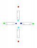
Here is a picture of what I am thinking of. I have 4 ceramic magnets. and some magnetic wire.
I was thinking that if I put the magnets like this in the picture then I would be able to have more contact at the same time because I would be getting the magnetic pull from the inside as well. From most designs that I have seen they ignore the inside poles of the magnets.
My question is, how do I set up the windings?
How do I connect them? Based on the pattern I use?
Ground?
In/out?
Direction of wind?
Is it possible to have more than 3 phases?
If I have 3 phases, how many armatures can I have for each phase?
That's where all the information seems to get a little confusing for me. It just doesn't lay it out clear enough for me to understand.
My understanding is that you need a north on one side of the link and a south on the other side of the link. Is this true? Could it not be changed with changing the direction of the winding?
For example, in my picture I have the magnets set up N,N,S,S in rotation. The reason I did that is so that the opposite side would have a clear opposite charge. But the issue with that comes with the uneven force on the magnets, where at some parts they would be pulling and other parts they would be pushing. Then say if I had it set up N,S,N,S on the inside and outside circles. and then just change my winding direction.
I am a little confused by what I am looking at. I'm trying to build a PM (permanent magnet) generator that will work on a hand crank.
I am trying to figure out how windings work and the setup of the armature design.
I was a video of a hand crank motor, that had the magnet on the inside of a cardboard box with tons of wire wrapped around. I am 100% certain I could do that. But to me that design seems very inefficiently. It wasted so much wire.
I thought you get energy from the turns. So it would make sense to have smaller turns to get more energy.
Here is a picture of what I am thinking of. I have 4 ceramic magnets. and some magnetic wire.
I was thinking that if I put the magnets like this in the picture then I would be able to have more contact at the same time because I would be getting the magnetic pull from the inside as well. From most designs that I have seen they ignore the inside poles of the magnets.
My question is, how do I set up the windings?
How do I connect them? Based on the pattern I use?
Ground?
In/out?
Direction of wind?
Is it possible to have more than 3 phases?
If I have 3 phases, how many armatures can I have for each phase?
That's where all the information seems to get a little confusing for me. It just doesn't lay it out clear enough for me to understand.
My understanding is that you need a north on one side of the link and a south on the other side of the link. Is this true? Could it not be changed with changing the direction of the winding?
For example, in my picture I have the magnets set up N,N,S,S in rotation. The reason I did that is so that the opposite side would have a clear opposite charge. But the issue with that comes with the uneven force on the magnets, where at some parts they would be pulling and other parts they would be pushing. Then say if I had it set up N,S,N,S on the inside and outside circles. and then just change my winding direction.
Attachments
Last edited:
