rafael_cordeiro
New Member
Hi all,
I am working in a simple project for my engineering course, but as I am not really very good at electronics, I have some sort of doubts. Hope you can help me out here, since it is a very simple project.
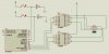
It is a very simple sttepper motor controller using a PIC 16F628A. When someone presses the first button it will turn in one direction, when the other is pressed it goes on the opposite way. I already tested the circuit together with the software I wrote in a simulation program. It all worked just very fine, but I have a few doubts.
**broken link removed**
1st - I´ve read in the ULN2003A datasheet that the outputs can be paralleled for higher output current (each output pin gives me 500mA, so with the three I would get 1500mA). Is this the right way to do it? Should I tie together only the outputs and not the inputs?
2nd - This PCB is ready already, because i am re-using it from a previous project that I gave up for a certain reason, before really testing it. I am a bit afraid to blow my PIC with the EMF generated by the sttepper. Can I use this circuit or should I make another PCB and use some diodes, some other resistors, etc?
Thanks a lot for any help.
Rafael Cordeiro
I am working in a simple project for my engineering course, but as I am not really very good at electronics, I have some sort of doubts. Hope you can help me out here, since it is a very simple project.
It is a very simple sttepper motor controller using a PIC 16F628A. When someone presses the first button it will turn in one direction, when the other is pressed it goes on the opposite way. I already tested the circuit together with the software I wrote in a simulation program. It all worked just very fine, but I have a few doubts.
**broken link removed**
1st - I´ve read in the ULN2003A datasheet that the outputs can be paralleled for higher output current (each output pin gives me 500mA, so with the three I would get 1500mA). Is this the right way to do it? Should I tie together only the outputs and not the inputs?
2nd - This PCB is ready already, because i am re-using it from a previous project that I gave up for a certain reason, before really testing it. I am a bit afraid to blow my PIC with the EMF generated by the sttepper. Can I use this circuit or should I make another PCB and use some diodes, some other resistors, etc?
Thanks a lot for any help.
Rafael Cordeiro