Continue to Site

Welcome to our site!

Electro Tech is an online community (with over 170,000 members) who enjoy talking about and building electronic circuits, projects and gadgets. To participate you need to register. Registration is free. Click here to register now.

  • Welcome to our site! Electro Tech is an online community (with over 170,000 members) who enjoy talking about and building electronic circuits, projects and gadgets. To participate you need to register. Registration is free. Click here to register now.

Need Help with Oscillator Circuit

Status
Not open for further replies.

headbuttking2

New Member
Hello, I frequent these forums alot, but this is my first actual post so please bare with me.

I have a garage door opener that operates at 310 MHz and I want to find a way that I will be able to switch between 310 MHz and 390 MHz.

Linear Corp (the makers of it) refuse to give me any help.
There is an IC made by semefab to linear corp's specs, but I can not get data from either of them, so I am pretty much left in the dark with that.

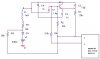
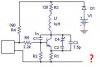
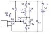
I drew the schematic of the oscillator from looking at the circuit, which looks to be a Collpit oscillator; however, I did not see the center tapped cap anywhere (I must have missed it).
As seen in the schematic I did on pspice, there is a variable cap inside of the netowork.

I could not get pspice to run a simulation on it either.
I am pretty new to it, and we just started using it in school, so I really do not have a very extensive knowledge on that.

If anyone can help me with this I would greatly appreciate it.
I need any help I can, especially how this works and what not.

Q1 is a KSP10 VHF/UHF NPN Transistor
D1 is an LED
The 5 V power should be 9 V, that was a mistake I made.

and I have no idea the capacitance of the variable capacitor

Thanks in advance,
Jim
 

Attachments

  • oscillator_129.jpg
    oscillator_129.jpg
    18.1 KB · Views: 1,076
Your drawing isn't correct, so can't work. I redraw to conventional arrangement. As You can see, not going to negative the emitter, inductor haven't parallel capacitor, etc. Check again.
 

Attachments

  • oscillator_129_188.jpg
    oscillator_129_188.jpg
    8.2 KB · Views: 1,100
Thanks for the help.
I will recheck it but I am still not sure where the center tapped cap is.

As for the new drawing, How could I get 390 MHz out of it?
 
The 320MHz "go out" from coil, and can work about 20...30 meter distance.
Maybe Your cct the following:
 

Attachments

  • oscillator_129_157.jpg
    oscillator_129_157.jpg
    8.4 KB · Views: 1,053
headbuttking2 said:
Thanks for the help.
I will recheck it but I am still not sure where the center tapped cap is.

As for the new drawing, How could I get 390 MHz out of it?

There is no tapped coil, the feedback is from collector to emitter, it's the usual crude 'vhf bug' type transmitter.

It's output frequency won't be very stable anyway, but it's set by the inductor, the associated capacitors, plus stray inductance and capacitance. It's such a crude circuit there's no way to calculate the frequency, as you've no way of knowing the inductance and capacitance values - but to increase the frequency you need to reduce the inductance or capacitance, or both. Again, the crude design may prevent you getting high enough, stray capacitance and inductance may make it impossible to reduce them enough - you can only try, and then measure the output frequency - preferably by using a suitable radio, a few yards away!.
 
Hi Sebi,
Shouldn't C1 be used to bypass the base of the transistor in your circuit so it is operating as a common base configuration like this?:
 

Attachments

  • sebi_s_oscillator_mod1.gif
    sebi_s_oscillator_mod1.gif
    10.9 KB · Views: 1,037
audioguru said:
Hi Sebi,
Shouldn't C1 be used to bypass the base of the transistor in your circuit so it is operating as a common base configuration like this?:

Yes, I would suggest he drew the circuit out incorrectly, it wouldn't work with a 1000pF from base to collector 8)
 
1 / (2 * pi * sqrt(L * C)) is supposed to give the resonant frequency. L = inductor, C = trim capacitor, sqrt = square root, and pi = pie, or
3.14 something.

seems to me this equation isn't always 100% correct. Others say it is because of extra capacitances experienced when transistors are used.

I don't know enough about transistors. Maybe Audioguru knows.
 
Hi Mstechca,
How can the formula be correct when the value of the inductor (which is shown way too high) and the tuning caps are next to nothing?
At these high frequencies that are nearly microwaves, just one inch of pcb trace is a resonant circuit. :)
 
I was ignoring all other factors. but that equation I said is just a generic equation. I figured there were other factors involved.
 
mstechca said:
I was ignoring all other factors. but that equation I said is just a generic equation. I figured there were other factors involved.

As I've already said, you can't calculate it because you don't know the values - however, your formula was correct, if you had any values to use it with!.
 
Wow, thanks for all the help.

Like I said, I did not know the value of the variable capacitor.
Most are in the pF range, so the pspice default of 1nF is prob really high.

As for the inductor, it is one that looks like a resistor.
It is green with bands: Brown, Black, Gold, Silver
I read somewhere they are read the same way as resistors but in uH.
If that is wrong please correct me.

As for the transistor capacitances:
the output capacitance = 0.7 pF
Collector Base Feedback Capacitance= 0.65 pF

I am guessing I can attach a 390 MHz opener to this and just have two boards in one opener....
I just thought it would have been much more convient to have one with a switch I can pop between 300 and 390 MHz.
 
headbuttking2 said:
Wow, thanks for all the help.

Like I said, I did not know the value of the variable capacitor.
Most are in the pF range, so the pspice default of 1nF is prob really high.

Usually they are something like 5-25pF - you could assume a fixed value of 15pF.

As for the inductor, it is one that looks like a resistor.
It is green with bands: Brown, Black, Gold, Silver
I read somewhere they are read the same way as resistors but in uH.
If that is wrong please correct me.

As for the transistor capacitances:
the output capacitance = 0.7 pF
Collector Base Feedback Capacitance= 0.65 pF

These are inconsequential, stray capacitance will be FAR higher than that, and stray inductance will be fairly high as well, compared to a 1uH coil.
 
headbuttking2 said:
What causes stray inductance and capacitance?

All the circuitry, an inductor is a piece of wire (or PCB track), a capacitor is two conductors with an insulator inbetween - your circuit is FULL of conductors, and the air and PCB inbetween are the insulators.

VHF construction is very critical, and this is bordering on UHF, where it's even more so!.
 
Status
Not open for further replies.

Latest threads

New Articles From Microcontroller Tips

Back
Top