Continue to Site

Welcome to our site!

Electro Tech is an online community (with over 170,000 members) who enjoy talking about and building electronic circuits, projects and gadgets. To participate you need to register. Registration is free. Click here to register now.

  • Welcome to our site! Electro Tech is an online community (with over 170,000 members) who enjoy talking about and building electronic circuits, projects and gadgets. To participate you need to register. Registration is free. Click here to register now.

Need Help with opamp Integrator Design

Status
Not open for further replies.

Acomp26

New Member
Hello,

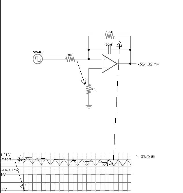
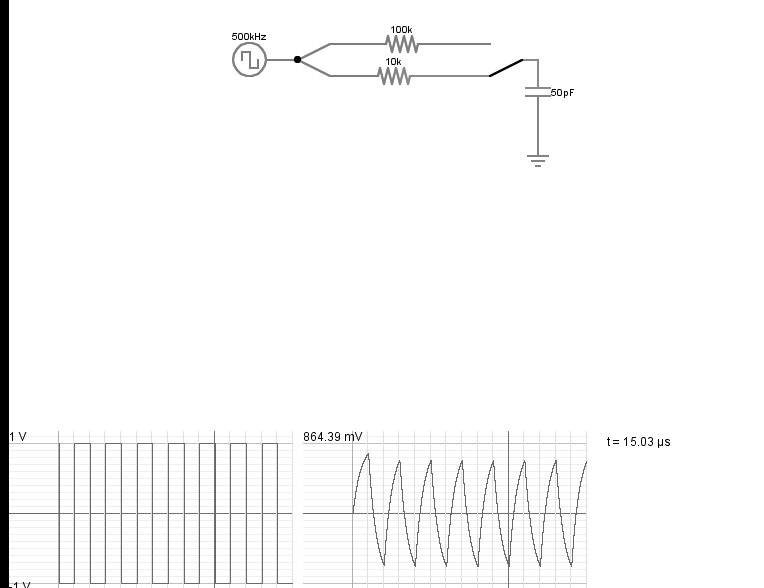
I'm very new to analog design and I'm trying to design an integrator. The integrator should be able to integrate a 10MHz signal and it should have very low noise. I was looking at a couple of opamps and I came across AD8066. It has very low input bias current, low noise, high 3dB BW and slew rate. I also considered OPA2355 (Probably better than AD8066?). I settled on AD8066 because I couldn't run transient simulations on OPA2355. (Don't know why, but kept failing) I used LTSpice to run the simulations. The integrator seems to work but I'm a little confused by the transient response. I have attached a .asc file.

Could anyone please help me with the design? Are there general set of design rules that can be followed for any integrator design?
 

Attachments

  • AD8066.asc
    1.6 KB · Views: 163
What about the transient response confuses you?
What output do you expect?
 
Thank you for the quick reply.

I was wondering why the transient output has no positive swing at all? Also why does it start at 0mV and drift to lower value as the time goes by? Also is the design of the integrator and opamp I have selected correct?
 

Attachments

  • Transient_ad8066.png
    Transient_ad8066.png
    43.5 KB · Views: 189
The drift is caused by the way Spice does a square-wave with finite rise and fall times. It subtracts from the low-time, making the square-wave slightly unsymmetrical. If you change the ON time to 99ns instead of 100ns, you will see less drift.

The integrator has a low output voltage for that input. Low output tends to increase the effects of any offsets in the circuit.
Is that all the voltage you need?
Why do you need to integrate such a high frequency?
 
I'm doing a project where the output of a high speed integrator has to be sampled at a particular rate. I don't know the exact output voltage requirement. I can always adjust the gain at particular frequency by changing R1,R2 and C right?
 
Also is the design of the integrator and opamp I have selected correct?
integrator?
What you drew has a DC gain of 10. And a gain at 10mhz of about nothing. Is that what you wanted to do?
I think of an integrator as having very high gain at low frequencies.
 
That circuit does integrate the 10MHz square-wave to give a sawtooth output but the time-constant is such that the output voltage is low.

Adjusting the values of R1, R2 and C will indeed change the gain of the integrator.
 
A simple LPF will integrate the 10 MHz to a triangle wave. A true Integrator will ramp the output with DC input offset.
 
I don't know what gain I want at 10MHz yet.

I also changed the R2 and C values to 10Meg and 1.2pF and got a gain of almost 0dB at 10MHz. Also why does the drift in the transient settle down after some time? (around 5us in this case)
 
I don't know what gain I want at 10MHz yet.

I also changed the R2 and C values to 10Meg and 1.2pF and got a gain of almost 0dB at 10MHz. Also why does the drift in the transient settle down after some time? (around 5us in this case)
It settles down after the integration capacitor is charged to whatever DC offsets there are from the amplifier or differences in the ON/OFF period.
 
It settles down after the integration capacitor is charged to whatever DC offsets there are from the amplifier or differences in the ON/OFF period.
But this does not mean that the settling time of the actual integrator circuit will be 5us right? This is only in the case of a Spice transient simulation.
 
With these new values the output of the integrator is not what I expected. For example if I feed a DC signal of 0.1V, I expect to get an output of (8.33e6*t). This is not happening. Could you please tell me why?
 
So what happens and what does not make sense?
 
But this does not mean that the settling time of the actual integrator circuit will be 5us right? This is only in the case of a Spice transient simulation.
The time-constant of the settling time is determined by the component values and the real circuit response should be quite similar to simulation.
 
I realized my mistake. I did not put a resistor from non-inverting terminal to ground. This was causing offsets to DC offsets to appear at the output. But how can we make the integrator very precise?
Define "very precise".
 
Last edited:
3339720100_1426191327.jpg


compute impedance (Z(f) of C at 500KHz and use that for gain. I used 9.1K on (+) to balance Vio due to I.in

Note passive version does not have constant current or linear slope near the integrator breakpoint.
8216346200_1426192037.jpg
 
Last edited:
Status
Not open for further replies.

New Articles From Microcontroller Tips

Back
Top