Continue to Site

Welcome to our site!

Electro Tech is an online community (with over 170,000 members) who enjoy talking about and building electronic circuits, projects and gadgets. To participate you need to register. Registration is free. Click here to register now.

  • Welcome to our site! Electro Tech is an online community (with over 170,000 members) who enjoy talking about and building electronic circuits, projects and gadgets. To participate you need to register. Registration is free. Click here to register now.

Need help with connecting and understanding the Ublox CAM-M8C GPS Module

Status
Not open for further replies.

Sashvat

Member
Hello everyone, I am using this Ublox CAM-M8C (Datasheet- https://www.u-blox.com/en/docs/UBX-15030063) GPS Module. I am connecting it to an ESP32 PICO D4 via UART, I have read the datasheet and I am a bit confused with how to connect it to my microcontroller and with understanding the module itself. I have made a schematic showing all my connections based on the "Minimal Design" section on page 10, Section 2.2, I am attaching it below. I have a few questions which I am listing below-

1) Is there only TXD (Pin 25) and RXD (Pin 26) required for UART or are there more connections that I have to make?

2) Does TXD on the GPS module need to connect to the global label RXD_GPS and vice-versa to the Microcontroller?

3) What does EXTINT do? What function does it have in a GPS module?

4) I have selected D_SEL to be open as I am running UART. I have given it a NC, the data sheet states that to use UART functions it needs to be open (pg.9, Pin 20), is what I have done enough, can I leave it right there?

5) What are Pins 3 and 6 (SDA/SPI_CS_N and SCL/SPI CLK)? Are they for UART?

6) What is TIMEPULSE (Pin 29)?

Thank you for your time and help!
 

Attachments

  • GPS-Sheet2.pdf
    25.1 KB · Views: 369
You only need the TXD and RXD to get the data, with D_SEL connected to the device positive power.
Cross connect TXD <> RXD between the GPS and MCU, with 220R series resistors near the GPS.

The other interface pins are for different types of interface and can be ignored.
See the "Minimal design" connections in figure 2-2 on page 10 of the datasheet.

Timepulse is the GSP "PPS" (pulse per second) output, used by some systems for extremely accurate timekeeping - a good GPS receiver sets its internal time to nanosecond accuracy, or even better.
Use it or ignore it!
 
You don't need to connect to RX on the GPS receiver.

You only need TX on the GPS receiver. When you connect power and ground, the GPS receiver will start transmitting NMEA data strings. The default Baud rate is 9600.

That is how a lot of GPS receivers are used.

This document https://www.u-blox.com/sites/default/files/CAM-M8-FW3_DataSheet_(UBX-15031574).pdf will answer most of your questions.

You can read data from the GPS using SPI or I2C. They are completely different protocols that use pins 3 and 6. That is an alternative way of getting data from the GPS receiver.

Timepulse will generally turn on once a second when the GPS receiver has acquired enough satellites. This is often connected to an LED so that it can be seen when the GPS has acquired satellites.

The baud rate and the timepulse rate can be changed if instructions are sent to the GPS receiver. However, I strongly recommend that you get the GPS working and your device receiving data from the TX pin of the GPS receiver before you try changing things.

Something like one of these:- USB - serial will read the data, and you can use a terminal emulator like RealTerm to read what the GPS receiver transmits.
 
You only need the TXD and RXD to get the data, with D_SEL connected to the device positive power.
Cross connect TXD <> RXD between the GPS and MCU, with 220R series resistors near the GPS.

The other interface pins are for different types of interface and can be ignored.
See the "Minimal design" connections in figure 2-2 on page 10 of the datasheet.

Timepulse is the GSP "PPS" (pulse per second) output, used by some systems for extremely accurate timekeeping - a good GPS receiver sets its internal time to nanosecond accuracy, or even better.
Use it or ignore it!
Thanks rjenkinsgb, is the timepulse something like a clock input for a connection to a crystal (HSE)?
 
You don't need to connect to RX on the GPS receiver.

You only need TX on the GPS receiver. When you connect power and ground, the GPS receiver will start transmitting NMEA data strings. The default Baud rate is 9600.

That is how a lot of GPS receivers are used.

This document https://www.u-blox.com/sites/default/files/CAM-M8-FW3_DataSheet_(UBX-15031574).pdf will answer most of your questions.

You can read data from the GPS using SPI or I2C. They are completely different protocols that use pins 3 and 6. That is an alternative way of getting data from the GPS receiver.

Timepulse will generally turn on once a second when the GPS receiver has acquired enough satellites. This is often connected to an LED so that it can be seen when the GPS has acquired satellites.

The baud rate and the timepulse rate can be changed if instructions are sent to the GPS receiver. However, I strongly recommend that you get the GPS working and your device receiving data from the TX pin of the GPS receiver before you try changing things.

Something like one of these:- USB - serial will read the data, and you can use a terminal emulator like RealTerm to read what the GPS receiver transmits.
Thanks Diver300, If I am right, then the TX of the GPS connects to the RX (input, GPIO pin) of my microcontroller and read data from it, the coordinates to the user. But then why do you need I2C or SPI when you are reading data from the TXD pins when they give NMEA data strings?
 
Thanks rjenkinsgb, is the timepulse something like a clock input for a connection to a crystal (HSE)?
No, it's and output for [accurately] incrementing the seconds counter in a real-time clock, in timekeeping applications.

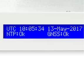
A common use is in conjunction with NMEA time messages in "NTP" master clocks; a software system that allows a clock to be near as accurate as an atomic clock. I have a GPS linked to a server PC in my loft that all my computers reference to, but it's not as accurate as it could be due to the varying PC load. I've recently put a dedicated timeserver unit together.


On your GPS, the other interfaces, SPI etc., are simply options for different types of system.
eg. SPI allows the GPS to be a slave device in a system and the data read only when required, rather than the GPS being the master on a serial link and continuously sending data that interrupts the controlling CPU or MCU.

Just stick with serial and ignore the rest, they are irrelevant for your application.
 
Thanks Diver300, If I am right, then the TX of the GPS connects to the RX (input, GPIO pin) of my microcontroller and read data from it, the coordinates to the user. But then why do you need I2C or SPI when you are reading data from the TXD pins when they give NMEA data strings?
You don't need the I2C or SPI. Those are just other features of the module. Most complex modules or ICs have features and connections that will only be used in some applications.

It may be possible to get data from the module faster using 12C or SPI. Using NMEA data strings, the data will be transmitted every second, and the normal strings will be a few hundred characters long. It will take 0.2 - 0.5 seconds for that data to be sent. It may be more convenient for some applications to read just some data using SPI or I2C, which will take much less time, probably less than 1 ms.
Ok, so where should I connect my microcontroller to this GPS module?
 
The module has a TX pin that sends a NMEA sting every second. That and power are the only connections you need.

Mike.

Isn't the RX useful as well, as you can (usually) send instructions via that - the usual one been to reduce the amount of data coming out in the NMEA string, most of which isn't needed (and most of what you're left with still isn't needed either, but at least it's smaller).

But certainly all you 'need' is the TX pin, power and ground.
 
the usual one been to reduce the amount of data coming out in the NMEA string, most of which isn't needed
True, however, as he's using an ESP32 ram is not a problem. I assume that data can be received on an interrupt and a flag set when a full string is available for parsing. If the OP was using a pic with 2k of ram then it would be a huge problem but not on an ESP.

Mike.
 
True, however, as he's using an ESP32 ram is not a problem. I assume that data can be received on an interrupt and a flag set when a full string is available for parsing. If the OP was using a pic with 2k of ram then it would be a huge problem but not on an ESP.

Mike.
So the data from the gps module is sent to the ram which has enough storage to store the GPS values, but had I used a PIC, with little memory then that would be a problem right? And if I was to use a PIC I need to add an external flash
 
So the data from the gps module is sent to the ram which has enough storage to store the GPS values, but had I used a PIC, with little memory then that would be a problem right? And if I was to use a PIC I need to add an external flash
It's RAM that matters, not flash.

Many older PICs had tiny amounts of RAM, a few tens of bytes - not enough to store a full line of text for a single NMEA "message".

Most newer ones have far more and would be fine; anything from eg. 512 bytes up should be useable, as long as there is enough for the other parts of the program.

The ones I'm working with at resent have anything from 16K to 48K RAM.

To give you an idea, this is a typical NMEA message string; as received, it's just a line of text:

$GPGGA,181908.00,3404.7041778,N,07044.3966270,W,4,13,1.00,495.144,M,29.200,M,0.10,0000*40

Whatever you are using needs enough RAM to be able to store a full line, verify the checksum and then split it up in to the different parts of the data and store those in individual variables.

And preferably have two line buffers so the next line can be received while the previous is being processed (aka "ping-pong buffering").

Hypothetically you could parse it as it is received and store the values as they come in, to keep the buffer requirements down - but handing the whole string is easier, if the CPU has the resources.

The example message string is from here; the page details the information included.
There are several other message types with different info.
 
So the data from the gps module is sent to the ram which has enough storage to store the GPS values, but had I used a PIC, with little memory then that would be a problem right? And if I was to use a PIC I need to add an external flash
You can receive GPS using a PIC without much memory. External flash memory wouldn't help you at all. It would be RAM that you need.

If you have a lot of memory, you can receive and store in memory all the NMEA strings that arrive in the data burst that arrives each second. When that has been captured, your program can look through the memory and pull out the data that you want.

Alternatively, if you only want certain data from the GPS string, it is possible to extract the data as it arrives, without storing the whole string.

Here is an example string:-
$GPRMC,161229.487,A,3723.2475,N,12158.3416,W,0.13,309.62,120598,,*10

The code to extract latitude and longitude would work something like this:-
1) When "$" is received, go to waiting for rest of string, even if the previous string wasn't finished
2) Wait for "G"
3) Wait for "P"
4) Wait for "R"
5) Wait for "M"
6) Wait for "C"
7) Wait for three commas
8) store the next two digits as the degrees latitude
9) store the next two digits as the minutes latitude
10) wait for the decimal point
11) store the next four digits as the fractions of minutes latitude
12) wait for a comma
13) wait for "N" or "S". If "S", mark latitude as negative
14) wait for comma
15) store the next three digits as the degrees longitude
16) store the next two digits as the minutes longitude
17) wait for the decimal point
18) store the next four digits as the fractions of minutes longitude
19) wait for a comma
20) wait for a "E" or "W" If "W", mark the longitude as negative

If you are working like that, you only need memory for one character at a time. You also need a pointer to say where in the data you have got to, and memory for latitude and longitude.

I have received data from GPS receivers using this method with PICs in several projects.
 
Hypothetically you could parse it as it is received and store the values as they come in, to keep the buffer requirements down - but handing the whole string is easier, if the CPU has the resources.
I agree that it is easier if the CPU has space. It's not hypothetical to parse the data as it arrives, because I have done it in both 8 bit and 16 bit PICs.

It can be difficult to debug code that it parsing the data as it arrives. It is a simpler concept to firstly store an entire string, and then have code that can parse that string without having to repeatedly wait for data.

When data is being received by a microcontroller with a USART, a byte will be stored in the USART buffer. The buffer length varies. I have used PICs with just one byte and others with 4 bytes. Any microcontroller that has a buffer smaller than a whole NMEA string will have to have code that collects data from the buffer and stores it in RAM while the string is still arriving.

If the whole string is to be stored, the code that collects data from the USART buffer and stores it in RAM will be very simple, but it will have to run often so that the buffer does not overflow.

If there is buffer of 4 bytes, and the data is being sent at 9600 baud, the buffer will overflow after just over 4 ms
 
It's not hypothetical to parse the data as it arrives, because I have done it in both 8 bit and 16 bit PICs.
I just did not want to get in to a detailed breakdown of something unrelated to the OPs project and have a possible multi-page back&forth on details of an irrelevancy!
 
The module has a TX pin that sends a NMEA sting every second. That and power are the only connections you need.

Mike.
Hello mike, I have just done it, power and txd_gps, is this the right thing?
 

Attachments

  • GPS-Sheet2.pdf
    19.6 KB · Views: 351
That look correct and the TX output should, of course, go to the RX pin of the processor. I suggest using UART1 on the ESP.

Mike.
 
That look correct and the TX output should, of course, go to the RX pin of the processor. I suggest using UART1 on the ESP.

Mike.
I just observed that this is the way to power the cam m8q but I am using the m8c, would that be fine?
 
Status
Not open for further replies.

Latest threads

New Articles From Microcontroller Tips

Back
Top