Continue to Site

Welcome to our site!

Electro Tech is an online community (with over 170,000 members) who enjoy talking about and building electronic circuits, projects and gadgets. To participate you need to register. Registration is free. Click here to register now.

  • Welcome to our site! Electro Tech is an online community (with over 170,000 members) who enjoy talking about and building electronic circuits, projects and gadgets. To participate you need to register. Registration is free. Click here to register now.

need help with CA led display

Status
Not open for further replies.

prosound90

New Member
hi

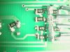
the ciruit has a PIC driving the (4) 7-sigments throw a ULN2003 and the

CA driven by a 2N3906 PNP transitor ,transistor vcc is 12V and PIC

vcc 5v from 7805T ,GND is shared for both vcc's ,transistor BASE resistor

is 1K and and a 100 ohm on each line between the 2003 and the

7 sigments,

now the problem that iam having the sink side is fine but the

PNP transistor's leaking to the displays (they are on with a logic 0 or 1 at

there base so my scaning program is not working and iam geting the same thing on all displays.

is it the 3906 week for driving a ca 1.8" diplays data sheet for display says 30 MA

should i use maybe a darlington PNP or ist somthing else

please help

thank you

i will try to post a schematic
 
Yes, please post the circuit - but it sounds like you're connecting the emitters of the PNP transistors to 12V, and the base to the PIC at 5V - so there's no way the transistors can ever turn off. To do this you need NPN opencollector drivers between the PIC and the PNP transistors.
 
thanks for replaying

you are right the emiters of the transistor are at 12 v to get some brightness.

so you think a pnp darlington transistor should work???.


iam posting the schematic check it out

thanks
 

Attachments

  • jumbo_clock.gif
    jumbo_clock.gif
    51.6 KB · Views: 464
prosound90 said:
thanks for replaying

you are right the emiters of the transistor are at 12 v to get some brightness.

Sorry?, I don't quite see that!.

It's current you need to make an LED brighter, the voltage across the LED remains pretty well constant. The only difference using a 12V supply will make is that the series resistor value will be higher than with a 5V supply to give the same current.

so you think a pnp darlington transistor should work???.

No, you need an NPN open-collector buffer between the PIC and the existing PNP driver. Like this:

Don't forget, this will give an extra inversion, and require changes to the software.
 

Attachments

  • 12v_sw.gif
    12v_sw.gif
    1.9 KB · Views: 451
i only used 12v to supply the anods because i could 'nt get the led displays to lightup at 5v thease are 1.8" digits.

any way thanks for the drawing but i want to ask you this is a work arownd to solve the problem that i have or its the comon way to drive CA
led display.....or there is a better way to drive a CA led just for future reffrence.


and yah what is the value for the resistor between the transistors.

thank you
 
prosound90 said:
i only used 12v to supply the anods because i could 'nt get the led displays to lightup at 5v thease are 1.8" digits.

Right, they may be more than one LED in series per segment - the specs on the display will tell you by their forward voltage drop/

any way thanks for the drawing but i want to ask you this is a work arownd to solve the problem that i have or its the comon way to drive CA
led display.....or there is a better way to drive a CA led just for future reffrence.

It's a standard way of high side switching a voltage higher than the processor supply, you find the identical circuit in many places - not just for LED's.

and yah what is the value for the resistor between the transistors.

They are not at all critical - I also left out a resistor in the collector of the NPN transistor (I'm suprised nobody has jumped on me yet!). You could use 4k7 for all of them - the missing one goes from the collector of the NPN to the base of the PNP.
 
Prosound - Have you considered using something like an ICM7218 IC to drive a multiplexed LED display? The IC contains all the segment decoders, drivers and multiplexing circuitry for 8 digits (including all decimal points). Using the IC eliminates the need for multiplexing the individual displays in Code on the PIC. You simply send the display data to the ICM7218 and move on.

Just a thought.

0x34
 
thanks guys its working fine now

(i wasted a few smd transistors from expermenting but thats ok this is how you learn)

the displys scans fine i think i just have to lower the value of the current limeting resistors to get it more bright ,cause you do lose some when its scand.


thanks again
 

Attachments

  • aut_0663.jpg
    aut_0663.jpg
    140.4 KB · Views: 357
Status
Not open for further replies.

Latest threads

New Articles From Microcontroller Tips

Back
Top