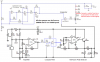
Continue to Site

Welcome to our site!

Electro Tech is an online community (with over 170,000 members) who enjoy talking about and building electronic circuits, projects and gadgets. To participate you need to register. Registration is free. Click here to register now.

  • Welcome to our site! Electro Tech is an online community (with over 170,000 members) who enjoy talking about and building electronic circuits, projects and gadgets. To participate you need to register. Registration is free. Click here to register now.

Need help with Bass Beat LED circuit

Status
Not open for further replies.

decev

New Member
Current Schematic:

**broken link removed**

The idea is to detect music from the electret mic, amplify it and send it through a low pass filter and full wave rectify it, and then smooth it to compare to a sawtooth wave, in order to drive some LEDs using Pulse width modulation. The point is to have the lights glow dimly when there is a low amount of noise and shine brightly when there is a loud noise.

The circuit works, sort of. It just needs a lot of fine tuning. One problem I have is that when I don't include c8, which is meant to be a smoothing capacitor, the LEDs flash visibly and rapidly. When I do include c8, they work well at full strength, but instead of glowing dimly at half strength, they flash slowly at a rate dependent on the value of c8. I then tried to attach a resistor in series with this cap, which produced very desirable results, only to fry my op amp after a few minutes use. The chip was not hot, but it did stop functioning, and had to be replaced. This happened twice, and I don't know whether it was the cap or the resistor that caused it. What I need help with here is either a better way to rectify and smooth the audio wave, or a way to include this without frying anything.

Another thing I wanted to do was to drive the LEDS a tiny by default, so they were always glowing, but the get bright during bass hits. I tried to do this by dividing the voltage at the "plus" input of U3A, in an attempt to base the audio wave at say 1V or 2V instead of 0V, but this didn't work. Is there any way to do this?

If anyone could give me ideas on either thing I would greatly appreciate it.

-Dave
 
Your mic needs 0.5mA of current. So the resistor that feeds it from 12V should be 24k ohms (use 22k), not 2.2k ohms. Or use 10k from 6V.

Your mic preamp has a very low input impedance of only 9.1k because it is an inverting opamp circuit type. It should have an input impedance at least 5 times the mic's resistor so it doesn't load down the mic. Therfore the opamp should be a non-inverting circuit type.

Your rectifier is half-wave, not full-wave, but it doesn't matter.

Your eyes need to see light for a minimum time of about 30ms. A half-cycle of 100Hz is only 5ms. So a peak detector circuit is needed.

Your vision's response to brightness is logarithmic, not linear. So half the current in an LED results in slightly reduced brightness. 1/10th the current looks half as bright. Try my circuit without converting the voltage to logarithmic.

Try this circuit:
 

Attachments

  • fixed bass beat circuit.PNG
    fixed bass beat circuit.PNG
    41.8 KB · Views: 1,360
The original mic preamp had a very low input impedance that was shorting the signal from the mic.
Yes Nigel, it was only 910 ohms.

The mic preamp and lowpass filter were not biased correctly so they passed their severe distortion to the rectifier.
 
audioguru said:
Try this circuit:

Thank you so much! This circuit looks just as good as my other one did, and none of my ICs are frying :D .

So what you are saying is that a logarithmic response would look more accurate to the eye than this one? I think I understand what you mean and I think you are right... there is a pretty low amount of middle ground when it comes to the sound level and the brightness of the LED. Most bass hits will push it to (apparent) max brightness. If you could give me ideas or send me a link I'll try to figure that out and give it a try, otherwise I'll try my best using google, but you saw how well that worked last time :eek:

I still have a couple more questions... is c8 in your circuit the capacitor that is holding the peak level? As it is now, the light response is pretty darn accurate, which sounds good but it is a little blinky and harsh on the eyes during some parts of some songs. Can I safely increase c8 to add a little afterglow to bass hits? Does R13 or anything else need to change with it?

Finally, I think I have to fix my triangle wave generator, because something isn't right. Correct me if I'm wrong, but it looks to me like the wave is being biased with about 2.8 volts, and so the LED should be on all the time, but it's not. I think I may have the amplitude of the triangle wave set wrong, which would make sense because I got the generator from another site. I've since found out how to modify the frequency, but I haven't found anything on the amplitude. Do you know the formulas?

Thank you so much
-Dave
 
decev said:
So what you are saying is that a logarithmic response would look more accurate to the eye than this one? I think I understand what you mean and I think you are right... there is a pretty low amount of middle ground when it comes to the sound level and the brightness of the LED. Most bass hits will push it to (apparent) max brightness.
Most bass beats and drums are at max volume so logarithmic doesn't matter.

If you could give me ideas or send me a link I'll try to figure that out and give it a try.
I have my Sound Level Indicator project running all the time. It is similar to what I attached except it is wideband without a filter and it uses an LM3915 10-LEDs bar driver IC showing a 30dB range of levels. It also has automatic-gain-control to show an additional 20dB without overloading. It is extremely sensitive to very low level sounds and bass beats light all 10 LEDs then a fade down between beats.

Is C8 in your circuit the capacitor that is holding the peak level?
Yes, but the 330k resistor discharges it so that it looks good on my 10 fading LEDs. Increase the value of the capacitor or the value of the resistor to increase the fading time for your single LEDs.

I think I have to fix my triangle wave generator, because something isn't right.
Its triangle-wave swings from 1V to 11V and is fine. It is biased properly at 6V.

Add a resistor across the transistor to make the LEDs glow a little when there isn't any sound.
 
Thank you. It looks great now. I wouldn't have been able to do it without your help. Is your automatic gain control circuit difficult to implement? I was thinking about trying something like that. If you think that it's overkill for this project that is fine too, otherwise I'll control the amplifier gain with a pot, which isn't as desirable but would still work.
 
For a volume control, connect R5 in my circuit as a 100k ohms to zero ohms rheostat. My automatic-gain-control uses extra transistors that are connected to the range control pins on the LM3915.
 
Here is my latest schematic for this circuit. It uses LM358 dual opamp ICs or LM324 quad opamp ICs that work without a negative supply and the supply voltage for the circuit can be from about +4V to +12V.
 

Attachments

  • corrected bass Beat Circuit.png
    corrected bass Beat Circuit.png
    120.5 KB · Views: 223
I think his old design fails because of oscillations with the cap on half wave out instead of full wave out on the feedback R, causing loss of phase margin. FWIW.

To increase dynamic range you can change last stage gain from 1 changing 100k to 1M and then add diode and 100k in parallel.

This makes it semi-log based on the principle of a log amp.
https://en.m.wikipedia.org/wiki/File:Op-Amp_Logarithmic_Amplifier.svg
 
The original circuit is full of errors which is why I fixed it. Look here:
 

Attachments

  • original bass beat circuit.png
    original bass beat circuit.png
    114.2 KB · Views: 190
i saw that it had neither sustain Cap or log gain, so I was just wondering
 
Most bass beat LEDs simply abruptly light brightly for each beat. I guess the author of this circuit uses PWM to smoothly brighten then smoothly dim the LEDs for each bass beat. I think a simple average detector will do it and the rectifier circuit is not needed:
 

Attachments

  • average detector.png
    average detector.png
    34.5 KB · Views: 167
Status
Not open for further replies.

Latest threads

New Articles From Microcontroller Tips

Back
Top