Continue to Site

Welcome to our site!

Electro Tech is an online community (with over 170,000 members) who enjoy talking about and building electronic circuits, projects and gadgets. To participate you need to register. Registration is free. Click here to register now.

  • Welcome to our site! Electro Tech is an online community (with over 170,000 members) who enjoy talking about and building electronic circuits, projects and gadgets. To participate you need to register. Registration is free. Click here to register now.

need help with automotive cornering light driver

Status
Not open for further replies.

CMil

New Member
Help, please! I'm kind of old to be just getting into the electronics hobby, but I've stepped into a project I just can't let go of! I want to add cornering lights to every vehicle in my garage, and I need help coming up with a workable driver or controller.
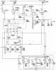
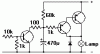
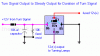
I know I'll need a relay for the light on each side of the car (2 relays), and each relay will need to be keyed by that side's turn signal. But how do I keep the relay pulled in with a "pulsing" signal? I've seen a circuit using a 555 IC timer, one using a 2N2222/2N3053 transistor, and one using nothing more than a 10,000 uF capacitor and a 1N4002 diode. I like the simplicity of the cap/diode circuit (the cap is wired in parallel with the relay coil, with +12vdc going through the diode, then through the anode of the cap). Anyone see a problem with such a circuit, or a way to improve without adding a mess of parts? Any/all input will be greatly appreciated. Thanks and God bless. - Chris
 
Ok the simplest thing if you have an automotive shop near by, you should get a thermalblinker relay. It's basically a relay with a heating element and sensor. Most cars use this and all you need to do is add the 12v lights in with the circuit and a couple switches and your set here are the schematics for my firebird that should give you an Idea. It has the entire schematic for wiring up the lights for everything but you just want to look at the Flasher Part. Thats one way to go if you want. But there are very many ways to do what you want.
 

Attachments

  • chassis_wiring_diagram__3_of_3_-1993-95_vehicles.gif
    chassis_wiring_diagram__3_of_3_-1993-95_vehicles.gif
    147.2 KB · Views: 4,686
Thanks, magickaldan. That's a good, complete wiring diagram; I think my Jeep is wired exactly the same way. I know it uses a GM steering column and turn signal switch.
I may not have been very clear in my original post, though. The cornering lights I'm trying to add would be in addition to the turn signals. Each cornering light (1 per side) would turn on and burn steady while the turn signal for that side blinked. In other words, left cornering light on constant while left turn signals flash, and same for right. Then, when the turn signal cancels, the cornering light turns off after a 4-6 second delay.
The steady burn and delayed turn-off are the key pieces of this puzzle (for me, anyway).
Hope this clarifies what I'm trying to accomplish. Thanks again, magickaldan, for the diagram. That's going to help me determine tie-in points. - Chris
 
for a steady burn, while the blinker is blinking... just tap the blinker circuit before it gets to the thermal relay... basicly the relay has 2 poles (at their simplest at least) ... power supply and output... power supply is always on, and output pulses on and off as a small heating element causes a circuit to make and break.

so if you tap your cornering lamp into the always on side of the blinker relay, your cornering lamp will be solid on as long as the blinker relay is receiving power.

the turn-off delay is slightly more complicated, and like you said, would require some sort of timer circuit controlling a relay... searching for a timer controlled 12 volt relay would be a good building block

**broken link removed**
 
CMil said:
Help, please! I'm kind of old to be just getting into the electronics hobby, ...

AH!! Never too old!!

And... if you are unlucky (guaranteed in electronics) then you might even manage to shave a few more valuable years from your life solving problems with the projects that you "just can't let go."
 
Glmcll.. I believe the blinker is before the turn switch, if it was after the switch you would need two of them, one right /one left.. I think the relay/cap idea that Cmil asked about is about the easiest, let the pulses from the turn signal keep the cap charged ,and when the signal is cancelled the relay will drop out a few seconds later..
 
Thanks, guys! True story - 1 flasher for 2 sides of the car. Now, here's another question - how much cap and diode do I need to make this happen? I'd like the cornering light to stay on 4-5 seconds after the turn signal cancels. Relay coil resistance is less than 100 ohms; will a 10,000 uF cap and 1 amp, 100 PIV diode co the trick, or should I look for something else? I'm willing to do a little trial and error, as long as it doesn't break the bank!
Thanks again for the input. Look forward to hearing from you again. - Chris
 
The 1a diode will work , the 10,000uf cap may be a bit high if you want 5-6 seconds. You can experiment with the cap value before putting unit in
car, my guess is you'll 2,200 to 3,300uf..
 
This circuit need for each side. The input coming from blinking lamp, the additional lamp continous burn, when input go low, after few seconds the lamp started fading,like indoor light in new cars. Depending from lamp power, need heatsink, or replace the lamp with relay.(no fading, no heat)
 

Attachments

  • delay_188.gif
    delay_188.gif
    2.2 KB · Views: 1,102
Increase the capacitance for a longer duration.BTW this is tested and works correctly.
 

Attachments

  • turninglights.gif
    turninglights.gif
    3.9 KB · Views: 2,115
Thanks a ton to you all! A question for Eclipsed - below the words, "+12V from turn signal", at the far left of the diagram, is that the 1A diode that Gerty says will work? With the white stripe on the right end, I would think it is, but I don't want to assume. Thanks again for the help, guys. - Chris
 
I used to work in a specialty vehicle repair facility where we routinely used 6A diodes to keep front and rear air conditioning controls from back-feeding each other. Would that "big" a diode be better in this application?
 
Looking at Eclipsed drawing you can see that the load will be about 200ma or less, depending on relay.. The diode isn't being used to supply power to the cornering lamp, just relay and resistor..
 
gerty said:
Looking at Eclipsed drawing you can see that the load will be about 200ma or less, depending on relay.. The diode isn't being used to supply power to the cornering lamp, just relay and resistor..
Yeah thats pretty obvious, now that I think about it.
 
What values would one suggest to use for the capacitor and resistor in order to get a one second off delay from this circuit?
 
Last edited:
how about a latching relay?
 
Status
Not open for further replies.

Latest threads

New Articles From Microcontroller Tips

Back
Top