I'm new here, hope this is the right forum to post this in. I can't read schematics very well. Nor do I know a lot of other fairly basic electronics stuff. Building portables (similar to Ben Heckendorn) and other things, I've actually never needed to learn how to read schematics and stuff. I learn as I go, really. I'm going to learn properly eventually, and I've tried my best to understand this tonight but I'm just not sure I know what I'm doing.
I'm trying to figure out how to put together this audio amp. The reason I'm confused is that there are so many different ways to use this amp that it's insane. Especially for a schematics noob like myself. A bunch of additional circuitry you can add to do other things. Currently, I have no interest in that. I just want to make the very basic amp. I'm going to use it as a microphone/input pre-amp for my computer. I don't care about all the little extra circuitry to make the signal cleaner or better or whatever. I just want it louder, see. I'm mostly going to use it for my microphone, but perhaps also for other audio sources.
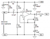
The image posted below is made from bits of the Datasheet. Please, do me the favor of downloading the actual datasheet at the link above and not basing all of your advice on this image. Because I'm not even sure if these are the important bits. This is just the stuff that I assume I need to be paying attention to.
**broken link removed**
Now, that simplified thing might not even be what I want. I don't know. But if it is, here's what I think I need to do. I have a 1/8" female jack. I would connect the positive of it to pin 3 and the negative to pin 2. I need a resistor to go from pin 1 to pin 8. Power would go into pin 7 and ground to pin 4. Now, I'm pretty sure the final, amplified audio signal comes out of pin 6. But where is the second connection for it? the "ground" for it? Do I use pin 4? Pin 2? Or is it pin 5 which is labeled "REF"? I have no clue what REF means.
Okay, now, as for the resistor, I don't know what sort of resistor I need. I really don't know anything about resistors and the datasheet lists all kinds of weird stuff so some help there is needed. Also, I'm not sure what voltage this thing needs to power it. I think it needs a minimum of 4.5 and has a maximum of 18. I might be wrong, but I assume the exact amount of voltage I want depends on the amount of amplification I'm going for. I'm sure that's what decides what resistor I need too, right? And honestly, I don't know anything about that stuff either. I just want a basic pre-amp for my computer and hopefully some one here is familiar with this stuff.
I'm sorry this post is so long. I'm sorry I'm so clueless as well. Any help will be very greatly appreciated.
I'm trying to figure out how to put together this audio amp. The reason I'm confused is that there are so many different ways to use this amp that it's insane. Especially for a schematics noob like myself. A bunch of additional circuitry you can add to do other things. Currently, I have no interest in that. I just want to make the very basic amp. I'm going to use it as a microphone/input pre-amp for my computer. I don't care about all the little extra circuitry to make the signal cleaner or better or whatever. I just want it louder, see. I'm mostly going to use it for my microphone, but perhaps also for other audio sources.
The image posted below is made from bits of the Datasheet. Please, do me the favor of downloading the actual datasheet at the link above and not basing all of your advice on this image. Because I'm not even sure if these are the important bits. This is just the stuff that I assume I need to be paying attention to.
**broken link removed**
Now, that simplified thing might not even be what I want. I don't know. But if it is, here's what I think I need to do. I have a 1/8" female jack. I would connect the positive of it to pin 3 and the negative to pin 2. I need a resistor to go from pin 1 to pin 8. Power would go into pin 7 and ground to pin 4. Now, I'm pretty sure the final, amplified audio signal comes out of pin 6. But where is the second connection for it? the "ground" for it? Do I use pin 4? Pin 2? Or is it pin 5 which is labeled "REF"? I have no clue what REF means.
Okay, now, as for the resistor, I don't know what sort of resistor I need. I really don't know anything about resistors and the datasheet lists all kinds of weird stuff so some help there is needed. Also, I'm not sure what voltage this thing needs to power it. I think it needs a minimum of 4.5 and has a maximum of 18. I might be wrong, but I assume the exact amount of voltage I want depends on the amount of amplification I'm going for. I'm sure that's what decides what resistor I need too, right? And honestly, I don't know anything about that stuff either. I just want a basic pre-amp for my computer and hopefully some one here is familiar with this stuff.
I'm sorry this post is so long. I'm sorry I'm so clueless as well. Any help will be very greatly appreciated.