Continue to Site

Welcome to our site!

Electro Tech is an online community (with over 170,000 members) who enjoy talking about and building electronic circuits, projects and gadgets. To participate you need to register. Registration is free. Click here to register now.

  • Welcome to our site! Electro Tech is an online community (with over 170,000 members) who enjoy talking about and building electronic circuits, projects and gadgets. To participate you need to register. Registration is free. Click here to register now.

need help with a simple 220V AC to 12V DC design

Status
Not open for further replies.

Heinbloed

New Member
Hello folks,
greetings from Germany im asking for help for a rather simple problem, i hope nobody feels offendet that im not really an electronic, allthough i try, i just recently bought a multimeter and a soldering iron:)
I want to build an air-cleaner, or a dust catcher, so to speak. i built a large 30cmx30cm filter and i want to use some large 140mm CPU fans, 4 of them, to pull the air through that filter. Those are high quality fans with good static pressure, and now i at least have a purpose for them. Now i need to find a way to hook them up, with a dimming option/potentiometer or something like that would be perfect. Easiest way would be to buy a Computer PSU ofc, but i think thats overkill both in size and price. I have some old small PSU in my boxes, common 5V or 12V, cant even remember where i got the from, 1 was from a shaver, 1 from an old DAC. I also have a slightly more powerful from a laptop, maybe theres a way i can mod one of them? Or is there some special Adapter/Voltage converter for that case? I couldnt find anything on Ali, at least nothing that has any terminals for that fans. and without terminals, i have no idea how to solder such a thing together. Maybe someone knows an easy way to realize that? The backside of the fan says 12V/0.3A.
thanks
 
Model number / photos of the fan and its connector - ?

Laptop power supply output ratings(s), and photo of the label - ?

ak
 
Your four fans need 0.3A each so 1.2A total. Simplest method would be a 12V 2A wall wart - check ebay. To control the speed of (computer) fans is normally done with PWM at 20kHz or higher so a potentiometer won't work and won't handle 1.2A. Do your fans have 3 or 4 leads?

Mike.
 
If you go with a DC power source that already is at the fan's max voltage, like a 12 V wall wart,, then an adjustable linear regulator will not get super-hot. My guess is a peak power dissipation of around 4 W when the fans are at 50% voltage. They will not srart reliably below that. An alternative is buying an adjustable buck regulator module on ebay.

ak
 
Hello folks,
greetings from Germany im asking for help for a rather simple problem, i hope nobody feels offendet that im not really an electronic, allthough i try, i just recently bought a multimeter and a soldering iron:)
I want to build an air-cleaner, or a dust catcher, so to speak. i built a large 30cmx30cm filter and i want to use some large 140mm CPU fans, 4 of them, to pull the air through that filter. Those are high quality fans with good static pressure, and now i at least have a purpose for them. Now i need to find a way to hook them up, with a dimming option/potentiometer or something like that would be perfect. Easiest way would be to buy a Computer PSU ofc, but i think thats overkill both in size and price. I have some old small PSU in my boxes, common 5V or 12V, cant even remember where i got the from, 1 was from a shaver, 1 from an old DAC. I also have a slightly more powerful from a laptop, maybe theres a way i can mod one of them? Or is there some special Adapter/Voltage converter for that case? I couldnt find anything on Ali, at least nothing that has any terminals for that fans. and without terminals, i have no idea how to solder such a thing together. Maybe someone knows an easy way to realize that? The backside of the fan says 12V/0.3A.
thanks

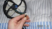
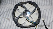
Please post a photo of one fan and its connector.
How do you intend for them to be controlled? Flip a switch and all turn on? Independent fan speed control or all the same speed?
 
i appriciate your efforts but i dont really understand what youre talking for the most part XD,,so the fans have 4 pins, but the also work with 3 pin. I found a splitter on ali which might be useful. Now i only need a powersource and a way to modify the speed. I checked my power supplies, they are all 3,7V or 9V. The Laptop PSU is 19Vdc and 7.1A. I have no problem ordering a new one, they are like 5eu on ali express. I just searched for 12V wall wart, seems thats another word for PSU? Would 12V 1A be a good Wall Wart? And how do i change the speed, even when i manage to hook them together? I dont need individual control, just need one turn to change their speed all together.

edit i also made a reading mistake, its only 0.2A, not 0.29A
 

Attachments

  • DSCI1708.JPG
    DSCI1708.JPG
    797.4 KB · Views: 287
  • DSCI1709.JPG
    DSCI1709.JPG
    832.8 KB · Views: 299
  • Unbenannt.PNG
    Unbenannt.PNG
    359 KB · Views: 293
Last edited:
I just searched for 12V wall wart, seems thats another word for PSU? Would 12V 1A be a good Wall Wart?
"Wall wart" is a word for a PSU that plugs directly into the wall.

12 V is correct for that type of fan. You need the PSU to have a larger current rating than the total of all of the loads. As they are 0,2 A each, it will take 0.8 A to run them all, so a 1 A power supply would be a good choice.
 
Diver300:
good, 12V 1A is 5 dolalrs on ebay. My 15V PSU would kill the fans you say? So that means i have to open that round connector and there will be a red and black wire in there? And what do i do to change the power/speed?


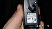
edit: update, i just found this 12V, 1,5A...glad i have so much crap in all different corners right now: I hope this can stand 24/7 usecase.
 

Attachments

  • DSCI1718[1].JPG
    DSCI1718[1].JPG
    736.8 KB · Views: 287
Last edited:
i appriciate your efforts but i dont really understand what youre talking for the most part XD,,so the fans have 4 pins, but the also work with 3 pin. I found a splitter on ali which might be useful. Now i only need a powersource and a way to modify the speed. I checked my power supplies, they are all 3,7V or 9V. The Laptop PSU is 19Vdc and 7.1A. I have no problem ordering a new one, they are like 5eu on ali express. I just searched for 12V wall wart, seems thats another word for PSU? Would 12V 1A be a good Wall Wart? And how do i change the speed, even when i manage to hook them together? I dont need individual control, just need one turn to change their speed all together.

edit i also made a reading mistake, its only 0.2A, not 0.29A
The cable splitter should work.
But you'll also need a Fan extension cable to plug into the female connector, so that you can make a "breakout" cable.
You will need to cut off the Female connector end of the extension cable, and strip the wires back, so you can connect or solder to the individual wires. Then...You'll also need a 12VDC, 1AMP minimum, Lamp Dimmer to control the FAN speed.

Google "1Amp DC lamp dimmer", and you'll get a lot of hits.
or
Google "12VDC Fan Speed controller"

Simplified connection diagram:
AC---DCSupply----->DCDimmer---->Ext cable----->1to4-Splitter------->fans(4x)

There might be a Dimmer that converts AC to 12VDC....

Your Fans are PWM compatible (4-wire) but you should be able to run them without PWM (steady DC).
A FAN part number world be good.

Found the part number: TY-147
"This fan is designed with PWM function, and full speed will apply when pluged into 3 pins instead of 4 pins ."
 
Last edited:
This site gives the wiring data for the fans. Black = Gnd, Yellow = +12V, Green = Tacho output, Blue = PWM input.
 
i already managed to get 1 fan running yesterday...:) i also tried the 9V power supply, was surprised it didnt work at all, i expected it to run at least at lower speed.
I already ordered something to regulate the speed, hope i didnt make a mistake..ordered a bunch of them, maybe ill need them in future builds.
 

Attachments

  • Unbenannt.PNG
    Unbenannt.PNG
    587.9 KB · Views: 278
Found the part number: TY-147
"This fan is designed with PWM function, and full speed will apply when pluged into 3 pins instead of 4 pins ."

does this mean the speed controller wont work when only attachen 2 cables? Theres only pos+ and neg- coming out of that PSUs. I think the PWM cable is for software control..there must be happening something when i turn on that wheel?
 
does this mean the speed controller wont work when only attachen 2 cables? Theres only pos+ and neg- coming out of that PSUs. I think the PWM cable is for software control..there must be happening something when i turn on that wheel?

Probably not - it's expecting a PWM signal on the PWM pin, and 12V on the power pin.
 
does this mean the speed controller wont work when only attachen 2 cables? Theres only pos+ and neg- coming out of that PSUs. I think the PWM cable is for software control..there must be happening something when i turn on that wheel?

Use the 3-wire version of the wiring. The 3-wire fan version has wires:+dc (red), -dc (blk), and tachometer(yel).
To test, Connect the fan +DC (red) to +DC of power supply and fan -DC (blk) to -DC of power supply.
If you then set the power suppy to 12v, the FAN will run at full speed. If you slowly lower the power supply voltage, the fan will slow down.

So....you want to connect the FAN +DC to the Fan controller +MOTOR and FAN -DC to Fan Controller -MOTOR so the Fan controller can vary the supply voltage to the FAN.

BTW-

The fan cable splitter will need to have a single 3pin fan connector to 4x 4pin fan connector for this to work correctly.
I think the one you showed in post #6 is incorrect. It is 1-4pin to 4x-3pin.
 
Last edited:
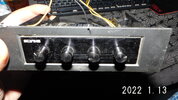
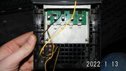
guys i have some concerning confessions to make XD..i didnt want to sit around and wait for all the china-components, so meanwhile i built the fancontrol out of my PC, i didnt really need it anyway. I hooked the power input of the Fancontroller to the 12V 1,5A wallwart...i also connected one fan..i was just realizing that the fan does not blow as it made "PUFF" and some smoke appeared. SO maybe i should have asked first, but i was under the impression i did everything right. The fans are 12V, so i thought 12V it is. Interesting is, in the PC the fancontrol was connected via Molex/sata connector. Im not sure but i think thats only 5V. As far as i know, only the GPU is connected on the 12V Rail. But how does that work if theres "12V" on the fan? Or was it too much current? I was thinking that the 1,5A on the wallwart is only the max rating and that the connected device creates the current....hmpff :(

id really like to know what happened there. cant see any obvious damage, but i was very obvious the fabcontrol wasnt happy.
 

Attachments

  • DSCI1726.JPG
    DSCI1726.JPG
    775.8 KB · Views: 269
  • DSCI1727.JPG
    DSCI1727.JPG
    792.2 KB · Views: 266
Which colour fan wire was connected where?
 
Status
Not open for further replies.

Latest threads

New Articles From Microcontroller Tips

Back
Top