Continue to Site

Welcome to our site!

Electro Tech is an online community (with over 170,000 members) who enjoy talking about and building electronic circuits, projects and gadgets. To participate you need to register. Registration is free. Click here to register now.

  • Welcome to our site! Electro Tech is an online community (with over 170,000 members) who enjoy talking about and building electronic circuits, projects and gadgets. To participate you need to register. Registration is free. Click here to register now.

Need help with a geared motor

Status
Not open for further replies.

crunch53

New Member
I need a little help on this. I think I found a motor assembly that will work for an application I am trying to do. This assembly is surplus and it looks like it’s out of a vending machine. I thought this thing would do what I wanted it to as is but it doesn’t seem to.
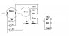
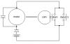
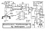
The cam is geared to the motor. The circuit shown is on a little circuit board setting next to the cam. T1 and T2 are just terminals sticking out of the board. It is a 6 to 24 volt motor. SW1 and SW2 are micro switches.
What I want to do is to be able to push SW2 and have the cam make one whole revolution and then stop until SW2 is pressed again. It would be nice to be able to just modify the circuit that is there but if you have a better way to do it let me know. Thanks
 

Attachments

  • vend_motor.jpg
    vend_motor.jpg
    13.8 KB · Views: 826
I think that's easy to do with a self holding relais. Pushing the switch SW2 closes the relais and 2 contacts of the relais are used to maintain the relais). The NC part of SW1 is then used to cut the power to the relais and the motor stops. A couple of buts are attached to this approach.

If you push SW2 too long the motor will keep running past the cam. And you need to push SW2 long enough to allow SW1 to close again.

I've added a sketch to clarify myself.

EJK
 

Attachments

  • image1_181.gif
    image1_181.gif
    5.9 KB · Views: 808
Try this. You have to press SW2 long enough for SW1 to close, and release it before a full rotation is finished.
 

Attachments

  • vend_motor2.png
    vend_motor2.png
    4.7 KB · Views: 769
You might try a small relay with an RC circuit to keep the contacts closed long enough to have the cam complete the circuit. The "R" in the RC circuit could just be the relay coil. You'd have to experiment a little to get the right value of "C". A low current requirement (high ohms) on the relay would help to keep the capacitor size down and reduce the "charge" time - which happens when the button is depressed. Crude but it might be good enough.
 
stevez said:
You might try a small relay with an RC circuit to keep the contacts closed long enough to have the cam complete the circuit. The "R" in the RC circuit could just be the relay coil. You'd have to experiment a little to get the right value of "C". A low current requirement (high ohms) on the relay would help to keep the capacitor size down and reduce the "charge" time - which happens when the button is depressed. Crude but it might be good enough.
What's wrong with the simple circuit I posted?
 
Ron H said:
What's wrong with the simple circuit I posted?

You mean apart from being converted from a poor quality JPG to PNG?, and thus been far larger than need be (and lower quality).
:lol: :lol: :lol: :lol: :lol: :lol: :lol: :lol: :lol: :lol: :lol: :lol: :lol:

But the circuit itself looks to be fine!.
 
Nigel Goodwin said:
Ron H said:
What's wrong with the simple circuit I posted?

You mean apart from being converted from a poor quality JPG to PNG?, and thus been far larger than need be (and lower quality).
:lol: :lol: :lol: :lol: :lol: :lol: :lol: :lol: :lol: :lol: :lol: :lol: :lol:

But the circuit itself looks to be fine!.
I can't handle criticism :!: :!: :!: :lol:
I wasn't aware that converting to PNG would make it bigger. I never claimed to be a graphics guru. :cry:
Anyhow, I cleaned it up and replaced it, just for the hell of it. (see above).
 
Thanks for the help. I am using Ron’s circuit and it works fine. I’m nor sure exactly what that little circuit does that is on the board but this works fine without it so I will probably take the parts off. Are the diodes necessary? Right now I am running it without them. Stevez is right, I do need something to keep the motor running for 2 to 3 seconds until the cam pushes the micro switch in for the rest of the revolution. I might be able to build the flat on the cam up a little bit but I would still need to do it for about a second. Any suggestions?
 
The "start" switch could be replaced with an SCR, the second switch would turn off the SCR by shorting it out. This would allow for very short duration presses of the starting switch. WE have similar ciruits on some electric actuators at work, the only difference is that the motor reverses at the end of a cycle.
 
Ron H said:
I wasn't aware that converting to PNG would make it bigger. I never claimed to be a graphics guru. :cry:

It only did because it was a crappy JPG in the first place, totally unsuitable for posting a diagram!. Converting it to a PNG only made it larger because of all the JPG rubbish in the image.

Anyhow, I cleaned it up and replaced it, just for the hell of it. (see above).

Now isn't that a LOT smaller, and perfect quality :lol:
 
If you add an relay in place of SW2 and a capacitor to hold the relay closed for a moment there is less concern for holding SW2 closed long enough for SW1 to be closed. A switch powering the relay still has to be held closed but not for long.
 
Nigel Goodwin said:
Ron H said:
What's wrong with the simple circuit I posted?

You mean apart from being converted from a poor quality JPG to PNG?, and thus been far larger than need be (and lower quality).
:lol: :lol: :lol: :lol: :lol: :lol: :lol: :lol: :lol: :lol: :lol: :lol: :lol:

But the circuit itself looks to be fine!.

I think Audioguru is starting to rub off on Nigel :lol:
 
Nigel Goodwin said:
Ron H said:
I wasn't aware that converting to PNG would make it bigger. I never claimed to be a graphics guru. :cry:

It only did because it was a crappy JPG in the first place, totally unsuitable for posting a diagram!. Converting it to a PNG only made it larger because of all the JPG rubbish in the image.

Anyhow, I cleaned it up and replaced it, just for the hell of it. (see above).

Now isn't that a LOT smaller, and perfect quality :lol:
Nigel, you've made my day. :lol:
 
jrz126 said:
I think Audioguru is starting to rub off on Nigel :lol:
A half-hour ago I took a small file size JPG photograph and converted it to a PNG file type like I do with most fuzzy JPG schematics. When I tried to attach it, this site said its file was too big. So I had to convert it to JPG again.
 
audioguru said:
jrz126 said:
I think Audioguru is starting to rub off on Nigel :lol:
A half-hour ago I took a small file size JPG photograph and converted it to a PNG file type like I do with most fuzzy JPG schematics. When I tried to attach it, this site said its file was too big. So I had to convert it to JPG again.

There's not much point converting a low quality JPG to PNG, but for posting drawings PNG or GIF are MUCH smaller and better quality. If you want good compression on picrures rather than drawings, JPG is probably still the way to go?.
 
Thats why I sent it that way in the first place. I'm not sure about this site but some of them limit you to maybe a 50K filesize. A BMP wont work. If you know of a better way to put stuff up to these sites let me know. I am fairly new to these forums. [/code]
 
Here's the 1st schematic I ever made on a pc. The original was a slightly fuzzy JPG so I continued modifying it as a JPG and it got fuzzier and fuzzier. If it started as a GIF or PNG then continued, it would look perfect.
 

Attachments

  • electronic_stethoscope_2_schematic.jpg
    electronic_stethoscope_2_schematic.jpg
    66.8 KB · Views: 590
crunch53 said:
Thats why I sent it that way in the first place. I'm not sure about this site but some of them limit you to maybe a 50K filesize. A BMP wont work. If you know of a better way to put stuff up to these sites let me know. I am fairly new to these forums.

If it's a diagram, drawn on your computer, post it as either a GIF or a PNG, these have no losses, and are far smaller than a JPG for those sorts of images. If it's a scan or photo, use JPG.
 
Even a circuit that complex takes only 7.45KB in GIF or PNG
 

Attachments

  • electronic_stethoscope_2_schematic_.png
    electronic_stethoscope_2_schematic_.png
    7.5 KB · Views: 571
Status
Not open for further replies.

Latest threads

New Articles From Microcontroller Tips

Back
Top