I've been working on a Computer controlled firing system for fireworks, and I thought my design was going to work... all my breadboard tests worked great, so I built a PCB, and now a problem has surfaced... went back to the breadboard, and sure enough the problem has been in the design all along. Without boring you completely with the intricate details of the control.. here's my problem.
The Plan:
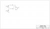
The plan was to use P-channel, and N-channel MOSFET's in series, one that would switch the ground, and the other that would switch the positives. This would allow me to have 8 n-channel mosfets switching the grounds, and 8 p-channel mosfets switching the positives... turning any two at a time on, would turn on a different combination of circuits, and eventually lighting a firework.
The Problem:
The problem seems to be that whenever I turn on one of the P-channel mosfet's, all the LEDs turn on (using LED's in place of fireworks for the time being... don't really want to blow myself up), regardless of what's going on with the n-channel ones. The most extreme case I tried was turning none of the n-channels on, and 1 of the p-channels on... and all the LEDs turned on. What I don't understand is why this would happen and how to fix it.
Attached is a simplified schematic of the circuit...
Any help would be appreciated.
Thanks
The Plan:
The plan was to use P-channel, and N-channel MOSFET's in series, one that would switch the ground, and the other that would switch the positives. This would allow me to have 8 n-channel mosfets switching the grounds, and 8 p-channel mosfets switching the positives... turning any two at a time on, would turn on a different combination of circuits, and eventually lighting a firework.
The Problem:
The problem seems to be that whenever I turn on one of the P-channel mosfet's, all the LEDs turn on (using LED's in place of fireworks for the time being... don't really want to blow myself up), regardless of what's going on with the n-channel ones. The most extreme case I tried was turning none of the n-channels on, and 1 of the p-channels on... and all the LEDs turned on. What I don't understand is why this would happen and how to fix it.
Attached is a simplified schematic of the circuit...
Any help would be appreciated.
Thanks