Hi there!
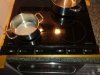
I have an AEG 618K induction stove. And it has been working excellently for 16 years!
Until the right side stopped working.
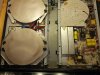
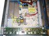
I really want to put this working again! Mostly because it's cheaper and more ecological. So I hope there is someone there that can help! (I upload image of the stove's inside.)
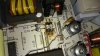
Opened it up and saw four burnt components (resistors R11 R12 and neighbouring transistors Q3 Q4, see uploaded images) on the main PCB. Got those through the internet, substituted them and turned it back on. (The resistors I bought are green 48 Ohm 1W power and a bit larger)
Result:
Just my luck; the left side went dead
But the right side worked fine... for three days :-(
Opened it up and Q4 definitely seems to have AGAIN a burn mark!
Action:
Wait for your advise on how to proceed with the right side.
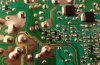
From comparison between the two identical PCBs I substituted on the left side the 68 kOhm R31 and R32 resistors(see image) as these seemed clearly to be off mark with a multimeter reading as compared to the color code and the left PCB board.
Result:
Right: on hold
Left: Back from the dead ... it worked fine for some days but then went zombie-like, because one zone works fine, the other zone works fine, but if I want to use both of them, then one just falls away (display starts to blink and after a while it disconnects, as if no pan was on it).
I remember some days ago having checked the relays on the power board feeding them the 24VDC and hearing every time the click of the circuit closing, so I thought all was well, but could it be that the contacts are worn out and no current flows? How to check this, should I apply the 24VDC and read the ohmage across the 240VAC part? Is the problem actually with the relays, or could it be their driving mechanism?
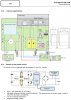
I also attach a technical image of the powerboard that might be of some assistance to someone willing to help, it is used in several brands' induction stoves.
Any advice here is very welcome.
R.A.
I have an AEG 618K induction stove. And it has been working excellently for 16 years!
Until the right side stopped working.
I really want to put this working again! Mostly because it's cheaper and more ecological. So I hope there is someone there that can help! (I upload image of the stove's inside.)
Opened it up and saw four burnt components (resistors R11 R12 and neighbouring transistors Q3 Q4, see uploaded images) on the main PCB. Got those through the internet, substituted them and turned it back on. (The resistors I bought are green 48 Ohm 1W power and a bit larger)
Result:
Just my luck; the left side went dead
But the right side worked fine... for three days :-(
Opened it up and Q4 definitely seems to have AGAIN a burn mark!
Action:
Wait for your advise on how to proceed with the right side.
From comparison between the two identical PCBs I substituted on the left side the 68 kOhm R31 and R32 resistors(see image) as these seemed clearly to be off mark with a multimeter reading as compared to the color code and the left PCB board.
Result:
Right: on hold
Left: Back from the dead ... it worked fine for some days but then went zombie-like, because one zone works fine, the other zone works fine, but if I want to use both of them, then one just falls away (display starts to blink and after a while it disconnects, as if no pan was on it).
I remember some days ago having checked the relays on the power board feeding them the 24VDC and hearing every time the click of the circuit closing, so I thought all was well, but could it be that the contacts are worn out and no current flows? How to check this, should I apply the 24VDC and read the ohmage across the 240VAC part? Is the problem actually with the relays, or could it be their driving mechanism?
I also attach a technical image of the powerboard that might be of some assistance to someone willing to help, it is used in several brands' induction stoves.
Any advice here is very welcome.
R.A.