Electro Tech is an online community (with over 170,000 members) who enjoy talking about and building electronic circuits, projects and gadgets. To participate you need to register. Registration is free. Click here to register now.
Welcome to our site! Electro Tech is an online community (with over 170,000 members) who enjoy talking about and building electronic circuits, projects and gadgets. To participate you need to register. Registration is free. Click here to register now.
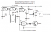
The first Cmos Schmitt-trigger gate is an inverter oscillator so that the probes are fed with AC to avoid plating on them which would happen with a DC signal.
The second and third gates produce a pulse-width-modulation output determined by the resistance (wetness) of the soil.
The 47k resistor and 22uF capacitor smooth the PWM waveform into a variable voltage.
the 4th gate triggers the transistor when the voltage drops to its Schmitt-trigger voltage level.
The transistor drives the relay for the watering pump.
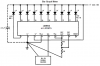
The LM3914 is a voltmeter that shows the filtered variable DC voltage which shows the wetness of the soil.
This site uses cookies to help personalise content, tailor your experience and to keep you logged in if you register.
By continuing to use this site, you are consenting to our use of cookies.