Continue to Site

Welcome to our site!

Electro Tech is an online community (with over 170,000 members) who enjoy talking about and building electronic circuits, projects and gadgets. To participate you need to register. Registration is free. Click here to register now.

  • Welcome to our site! Electro Tech is an online community (with over 170,000 members) who enjoy talking about and building electronic circuits, projects and gadgets. To participate you need to register. Registration is free. Click here to register now.

NEED HELP! Push button toggle circuit

Status
Not open for further replies.

LTD566

New Member
Hello!

I am new to the forum and I have been trying to put together a circuit for the past couple days with no luck and have just about gone crazy...

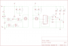
I need to be able to control 3 individual LEDs with one push button.

For example, I push the button once, LED 1 comes on. I push the button again LED 1 goes off and LED 2 goes on. I push the button again, LED 2 goes off and LED 3 goes on. I push the button again, LED 3 goes off. I push the button again and the cycle starts back at LED 1...

I am not 100% electronic literate, although I have taken basic electronic courses, so for the most part I can understand and intemperate circuit diagrams.

I wish to keep the circuit as basic as possible, with most of the components being available at radio shack, or online.

PLEASE, ANY help would be appreciated! Even if someone knows of a similar circuit that I could start off with looking at would be great.

Thanks!
 
Last edited:
Do you have access to a three terminal button? If answer is yes, you can avoit using timing circuits and just use a simple SR latch.

If not, then you have to make a monostable circutit that can wait some milliseconds to avoid multiple hit (it always happends on smapp push buttons). But then of course, a small 555 timer is pretty easy to make and doesn't recuire too many components.

This circuit is going to be controlled remotely, so unless I place in a servo to control the switch, the three terminal switch is not an option...

Is there a diagram somewhere that shows how I would use a 555 timer to do something like this?
 
Hi LTD556,

here is a circuit which might suit your needs.

It consists of two PCBs. Board1 is the "transmitter" containing a push button and a debounce circuit.

Board2 contains a decimal counter which advances one count each time the button is pressed.

At the fourth count the circuit is being reset and all LEDs are off.

Here are schematic and two small board designs. Both boards connect via a 3 wire cable or a 6 wire ribbon cable (+UB, Clock signal and ground).

Boncuk
 

Attachments

  • 3LEDs-schematic.png
    3LEDs-schematic.png
    56.1 KB · Views: 323
  • 3LEDS.png
    3LEDS.png
    36.6 KB · Views: 275
Last edited:
As another option you could use a little 8 pin Picaxe chip (08m2 chip) and some simple code like this to do the full job.

The pause 100 will give a 100 millisecond delay to allow for switch bounce, and human reaction time, while the "inc" will increase a internal counter register by 1 each time the switch is pressed, the rest is basically as it reads in English.

If the counter is equal to 1 then turn off led 2 and led 3 and switch on led 1...end of instruction.

if the counter is not equal to 1 then it will skip the instruction and go to the next instruction and so forth till it reaches the "goto main" and then it loops back to "Main" and starts over again.

Simple as 123.

If you would like to use a micro processor like this i will do a schematic to suit, but its not much more than 1 chip and a couple of resistors. (it will need a 5 volt supply)

The advantage with using a micro is if you want to change a function then its just a few lines in the code to change and reload the code, no need to change the hardware.

Lets say you wanted to flash a led a few times when the button was pressed then its just a matter of adding a few lines of code to do it, the circuit remains the same.

Pete.


Code:
#picaxe 08m2

Symbol button_switch = 	pinC.3
Symbol led_1 =		C.0
Symbol led_2 =		C.1
symbol led_3 =		C.2

Symbol counter = 		b1

low led_1, led_2, led_3

Main:


	if button_switch = 1 then
	inc counter
	pause 100
	endif
	
	if counter = 1 then
	low led_2, led_3
	high led_1
	endif
	
	if counter = 2 then
	low led_1, led_3
	high led_2
	endif
	
	if counter = 3 then
	low led_1, led_2
	high led_3
	endif
	
	if counter = 4 then
	low led_1, led_2, led_3 
	counter = 0
	endif
	
	goto main

EDIT:-

Here is a schematic to show how simple it can be with a Picaxe.
If the leds need more than 20mA the a drive transistor will need to be added for each led.
The programming socket is a standard D9 serial socket, no fancy programming board required.
 

Attachments

  • 3 led toggle schematic..JPG
    3 led toggle schematic..JPG
    44.4 KB · Views: 289
  • 3 led toggle schematic.pdf
    11.9 KB · Views: 161
Last edited:
Here's a simple solution, use a LM4017 decade counter. Data sheet is readily available. There are ten sequenced outputs and a reset pin (this is what 'restarts' the count) Using 9vdc supply and 3x 680 Ohm resistors connected ro the output pins 3(LED#1),2(LED#2) & 4(LED#3) connect the LEDs anodes to the n/c end of the resistors and the cathodes to gnd. (see the datasheet for examples) The 'clock' pin is #14. By sending a high logic pulse (your momentary pushbutton connected to V+) you advance the counter and the next LED illuminates. Pin 7 is the '4th' in the count order, so connect the 'reset' pin (#15) to pin 7 and the counter is reset and the output to pin 3 goes high again(LED#1). It is a very simple circuit and can be expanded easily - and driven by something like a LM555 if you wanted an automatic/timed sequence of ten LEDs. I have used this circuit hundreds of times for sequence indicators, with regular pushbuttons (n.o.) on machinery, etc....works great.
 
Here's a simple solution, use a LM4017 decade counter. Data sheet is readily available. There are ten sequenced outputs and a reset pin (this is what 'restarts' the count) Using 9vdc supply and 3x 680 Ohm resistors connected ro the output pins 3(LED#1),2(LED#2) & 4(LED#3) connect the LEDs anodes to the n/c end of the resistors and the cathodes to gnd. (see the datasheet for examples) The 'clock' pin is #14. By sending a high logic pulse (your momentary pushbutton connected to V+) you advance the counter and the next LED illuminates. Pin 7 is the '4th' in the count order, so connect the 'reset' pin (#15) to pin 7 and the counter is reset and the output to pin 3 goes high again(LED#1). It is a very simple circuit and can be expanded easily - and driven by something like a LM555 if you wanted an automatic/timed sequence of ten LEDs. I have used this circuit hundreds of times for sequence indicators, with regular pushbuttons (n.o.) on machinery, etc....works great.

Hi,

the circuit as described might work for you.

It won't work for the OP though. He wants LED1 on when the remote push button (supplying the clock signal) is pressed. With the next clock cycle LED1 should be off and LED2 is on and so forth until the LED3 will be on. Finally with one more button push all LEDs should be off.

According to your description LED1 will be on after reset (which doesn't initiate count, just reset), but after a reset all LEDs should be off. So output Q0 (pin3) must not be used for the application.

Boncuk

Okay then, leave pin2 (was LED#1) n/c,then use pin4(LED#1) Use pin7(LED#2) Use pin10(LED#3) and pin #1 (fifth in the sequence)goes to reset. That way you get a 'no lights until a button is pressed' after reset schema. I failed to understand that the user wanted to cycle 1,2,3 and then all LEDs off :) My misunderstanding. Otherwise the circuit is the same.
 
What should I say?

RTFQ!

Boncuk
 
Status
Not open for further replies.

New Articles From Microcontroller Tips

Back
Top