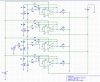
my team are doing on tactile auditory sensory substution (a hearing aid for high frequency hearing disablities) and we are completey noob in engineering and the project is due in 4 weeks time, so we really need some help and guidance. We so far set-up the band-pass filters, and we are now doing the comparators so we can activate the filters once vref has been set for each. Thing is what we need help is:
- how to set the vref according to the voltage of the circuit
- how to set the threshold
- how to set the voltage divider? variable resistor? or two resistors? if resistor, how do we calculate?
- does LM386 amplifies external signal?
- will an LM741 used as an audio amplifier?
- and we are not sure why our filter is not consistent in giving the output signal.
Thats all we need to know, and trust me i did the research on wikipedia, ourserve.com everything.. and we do not have textbooks, cause we doing PBL, thats why we are suffering. pls help! pls pls..all we need is tips and guidance of basic analog circuits
- how to set the vref according to the voltage of the circuit
- how to set the threshold
- how to set the voltage divider? variable resistor? or two resistors? if resistor, how do we calculate?
- does LM386 amplifies external signal?
- will an LM741 used as an audio amplifier?
- and we are not sure why our filter is not consistent in giving the output signal.
Thats all we need to know, and trust me i did the research on wikipedia, ourserve.com everything.. and we do not have textbooks, cause we doing PBL, thats why we are suffering.
pls help! pls pls..all we need is tips and guidance of basic analog circuits
Last edited: