johnny ace
New Member
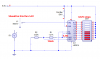
I used the datasheet for the LED driver and copied the circuit on page 2. It said that the range for the circuit is 0-5V, however when i built it, the range was about 0-1V. Did i draw the circuit correctly?

Likewise for page 11.
could not get it right.

I eventually want to build a circuit with an adjustable upper and lower voltage limit so that I can expand/shrink the range or shift it with pots.
Likewise for page 11.
could not get it right.
I eventually want to build a circuit with an adjustable upper and lower voltage limit so that I can expand/shrink the range or shift it with pots.